Notes on AllStarLink USB Audio Interfaces
Random notes from study of the mechanisms involved in creating a driver for a USB audio interface. Some of this is probably just general Linux USB knowledge.
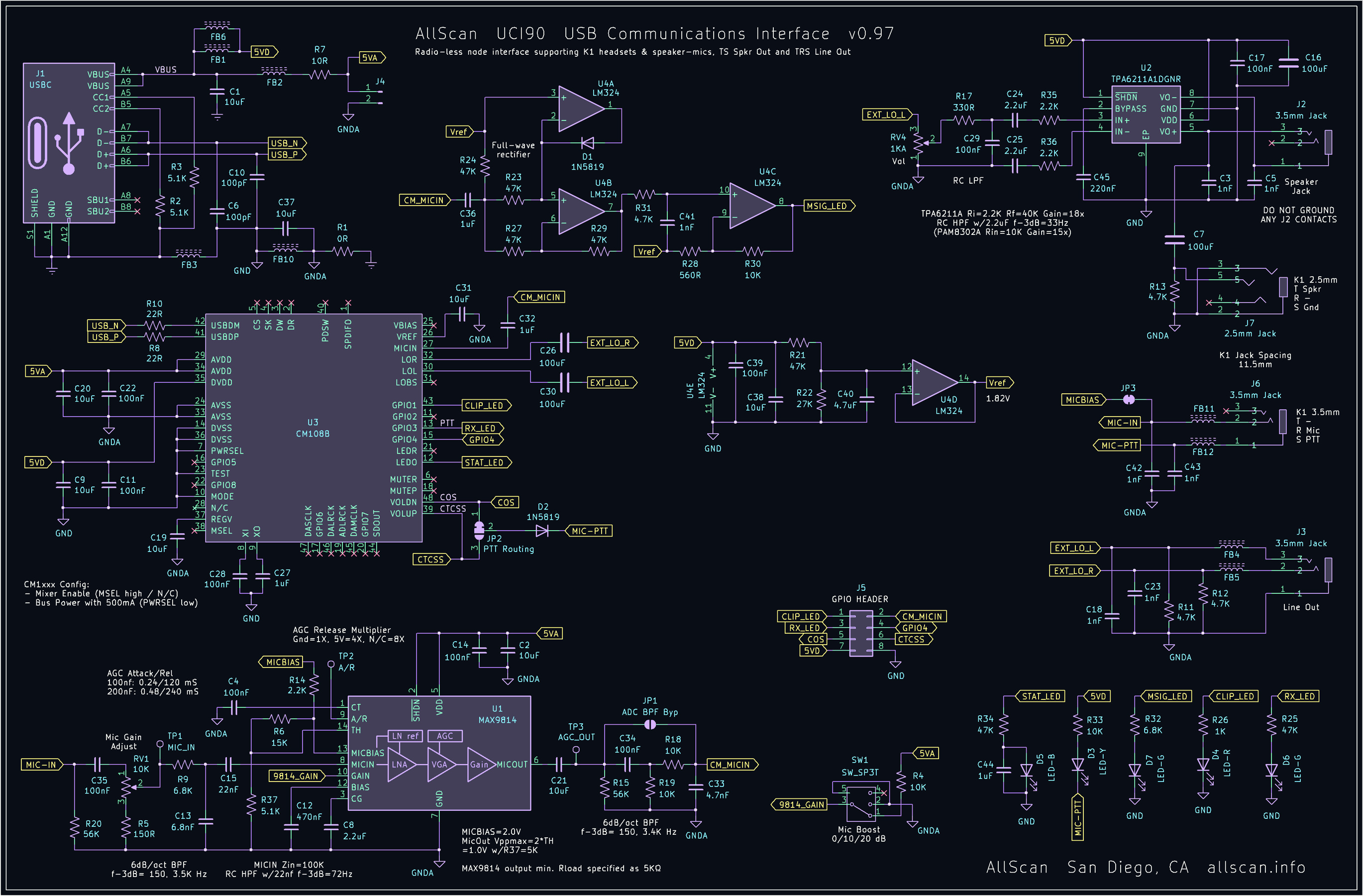
HID Experiments With an AllScan UCI90
Many thanks to David Gleason for sending me one of these excellent devices. See AllScan.info. This device uses the CM108B chip.
- Schematic for the UCI90
- Datasheet for the CM108B
- See this page for information on Linux USB controls.
My testing was done on a Raspberry Pi 5 using the stock OS. No special drivers we required to use the UCI90.
The CM108B chip allows GPIO pins to be read via USB HID registers. Here’s the code that can read 4 bytes of data out of the box via the HID interface. From the Linux docs “typically, this is used to request the initial states of an input report of a device, before an application listens for normal reports via the regular device read() interface. The format of the buffer issued with this report is identical to that of …“
  char buf[64];
  // Set the report ID
  buf[0] = 0;
  int ret = ioctl(fd, HIDIOCGINPUT(5), buf);
  // The first byte is the report ID, ignore it
  for (unsigned i = 1; i < ret; i++)
      printf("%d %02X\n", i, (unsigned int)buf[i]);
The PTT button on the microphone (connector K1 3.5mm) acts like a COS signal. This is connected to the VOLDN pin (pin 48) on the CM108B. This maps to HID_IR0 bit 1. So if the microphone button is pressed we’ll get this from the ioctl() call:
0x02,0x00,0x00,0x00
Whenever the GPIO state changes a USB HID interrupt is generated. This can be accessed using a normal read() system call - no ioctl() required. The format of the data is the same - 4 bytes.
The CM108B is a stereo CODEC so the audio data needs to be stereo. That said, we usually only care about one channel. The audio output on the speaker connection of the UCI90 (J2) and the microphone connection (K2 2.5mm) comes from the left channel of the CODEC (pin 30).
The audio input from the microphone connection appears on both channels at the same time.
HID Experiments With USB Audio Box Containing a CM6206
This device is reported as “CM106 like” by the Linux kernel.
We are reading/writing /dev/hidraw0 in all cases, using normal Linux open/read/write calls. There is no ioctl necessary with this chip.
Per USB specification, numbers are represented in little-endian format.
Test 1: Press/release mute button on control box. Output:
0x14, 0x00, 0x30 -> 0001 0100, 0000 0000, 0011 0000 0x10, 0x00, 0x30 -> 0001 0000, 0000 0000, 0011 0000
This shows the “mute” bit turning on/off (WORKING!).
Test 2: Press/release volume down button. Output:
0x12, 0x00, 0x30 0x10, 0x00, 0x30
This shows the “VDN” bit turning on/off (WORKING!).
Test 3: Generate a Set Output Report asking for the contents of
register 1.
Send 48, 00, 00, 01. Received 0x30, 0x00, 0x30 -> 0011 0000, 0000 0000, 0011 0000
From datasheet (page 19), this means PLLBINen=1 and SOFTMUTEen=1.
Test 4: Read register 3.
Send 48, 0, 0, 3 Received: 0x30, 0x7F, 0x14
Full register 3 contents: 0001 0100 0111 1111
Notes on Audio Flow Through chan_simpleusb.b
Channel function simpleusb_write() is called when a data frame is received from the network. This function does nothing more than put the frame onto o->txq for later handling.
Channel function simple_read() appears to be called periodically (at the frame rate?) and does a few things:
- (A few steps)
- Takes frames off the transmit queue (o->txq):
- Applies preemphasis, converts to 48k audio,
- Sends them to the sound card.
- Reads from the sound card to get as much as possible
- If there is no audio available then return immediately with a null frame.
- Based on COS/CTCSS status (and transitions) sends control messages AST_CONTROL_RADIO_KEY or AST_CONTROL_RADIO_UNKEY.
- Converts the 48k sound to 8k, makes a frame, deals with HPF, deemphasis, etc.
- DTMF detection: ast_dsp_process(c, o->dsp, f) that appears to return a frame handle if there is any DTMF content in the audio frame.
Linux Audio Interface (USB)
res_usbradio.c looks into this directory:
/proc/asound/cards
Setting/Getting HID Register:
void ast_radio_hid_set_outputs(struct usb_dev_handle *handle, unsigned char *outputs)
{
	usleep(1500);
	usb_control_msg(handle,
        // Request Type
        USB_ENDPOINT_OUT + USB_TYPE_CLASS + USB_RECIP_INTERFACE,
        // Request
        HID_REPORT_SET,
        // Value
        0 + (HID_RT_OUTPUT << 8),
        // Index
        C108_HID_INTERFACE,
        // Data
        (char *) outputs,
        // Length
        4,
        // Timeout
        5000);
}

void ast_radio_hid_get_inputs(struct usb_dev_handle *handle, unsigned char *inputs)
{
	usleep(1500);
	usb_control_msg(handle,
        // Request Type
        USB_ENDPOINT_IN + USB_TYPE_CLASS + USB_RECIP_INTERFACE,
        // Request
        HID_REPORT_GET,
        // Value
        0 + (HID_RT_INPUT << 8),
        // Index
        C108_HID_INTERFACE,
        // Data
        (char *) inputs,
        // Size
        4,
        5000);
}
int usb_control_msg(struct usb_device * dev,
    __u8 request,
    __u8 requesttype,
    __u16 value,
    __u16 index,
    void * data,
    __u16 size,
    int timeout);
Get Request Type: 0b1010_0001 (0xA1), request: 0x01, value: 0x0100, index: 0x0003, length: 0x0004 Set Request Type: 0b0010_0001 (0x21), request: 0x09, value: 0x0200 #define C108_HID_INTERFACE 3
Understanding request parameter:
USB_ENDPOINT_OUT + USB_TYPE_CLASS + USB_RECIP_INTERFACE
From libusb docs:
- Bit 7: Data Transfer Direction (0 = Host to Device, 1 = Device to Host)
- Bit 6-5: Type (00 = Standard, 01 = Class, 10 = Vendor, 11 = Reserved)
-
Bit 4-0: Recipient (00000 = Device, 00001 = Interface, 00010 = Endpoint, 00011 = Other)
- USB_ENDPOINT_OUT (0x00): A transfer from the host to the device.
- USB_ENDPOINT_IN (0x80): A transfer from the device to the host.
- USB_TYPE_CLASS: corresponds to the value 0x01 « 5 (which is 0x20), meaning the bits 6 and 5 are set to 01. This signifies that the request is a class-specific request.
- USB_RECIP_INTERFACE (0x01): The request is directed at one of the device’s interfaces.
Understanding request parameter:
    HID_REPORT_SET - 0x09 0b0000_1001
    HID_REPORT_GET - 0x01 0b0000_0001
Understanding “value” parameter:
    0 + (HID_RT_OUTPUT << 8),
    0 + (HID_RT_INPUT << 8),
Possibly: HID_RT_INPUT = 0x01; HID_RT_OUTPUT = 0x02. So HID_RT_OUTPUT « 8 = 0x0100 and HID_RT_INPUT « 8 = 0x0200?
USB Audio Experiments
Looking in /dev/snd. The naming convention pcmCxDy or controlCxDy indicates the card number (x) and device number (y) for a specific sound card. ”p” for playback, “c” for capture.