Ampersand Linking Project
The purposes of this project:
- To provide hams with a simple way to link radios to the AllStarLink network. Radio-less applications are also supported (conference hubs, direct audio connections, etc.).
- To provide a platform for research and experimentation to advance the state-of-the-art around ham radio linking.
- To maintain compatibility with the rest of the ASL ecosystem. This is not a fork of ASL or an attempt to create a parallel network. I don’t know all the history since I’m relatively new to this, but it appears there is a lot of drama/feuding in the AllStar space. I’m keen to stay away from any of the drama.
This project was originated in October of 2025 by Bruce MacKinnon (KC1FSZ) of the Wellesley Amateur Radio Society in Wellesley, MA. Please reach out using the e-mail address provided in QRZ. You can try me on AllStar node 672730, as long as I’m not in the middle of a compile. I’m also on LinkedIn.
The original thread where this was introduced is located here.
I’m not an expert on AllStarLink. I just got into this in late 2025. I’ve given a few talks at Amateur Radio clubs on this work and I’d be happy to dial into your club meeting if you want an overview of what this project is all about.
Table of Contents
- Table of Contents
- Introduction
- Users/Installation Guide
- Credits
- Current Work In Process
- Other Links
- Ampersand Server User Interface
- Conceptual Model of the Ampersand Server
- Technical Information
- Software Architecture
- IAX2/ASL Network Protocol Notes
- Network Information
- ASL Node Registration
- ASL Node Query
- Downloading the ASL Node Database
- ASL Statistics Posting
- Other Intel on ASL Registration/Stats
- Determining the IP Address of a Public Node
- An Alternate Authentication Mechanism: Web Transceiver
- IAX2 Audio Notes
- Notes on Initial Handshake
- Ongoing Handshake
- IAX2 Message Flow Examples
- Sequence Number Notes
- IAX2 Message Format/Semantics
- Protocol Notes Related to M1KE Devices.
- CODEC Negotiation
- The AMI Protocol
- Dropping All Connections
- Firewall/CGNAT Traversal
- Protocol Extensions
- Microcontroller Version
- VOTER Implementation
- Other Pages
- References/Books
Introduction
There are well established ways to get on AllStarLink using the ASL3 package and the Asterisk open-source PBX. Asterisk is a sophisticated system intended for a broad set of telephony applications. As such, it can be hard to understand, hard to configure, and hard to enhance. The Ampersand project is focused on supporting a minimal set of capabilities needed by hams.
The Ampersand project is not attempting to replace Asterisk. There are 1000’s of successful Asterisk installations being used by hams and that isn’t expected to change. My hope is that Ampersand will provide a better platform for experimental work. There are already a few features in Ampersand that are not available in Asterisk.
Users/Installation Guide
There are a few different components, each with its own guide:
- Please see The Ampersand Server User’s Guide for installation instructions on Linux. This is the package that most people care about. Thanks to David (NR9V) for his assistance with the design and testing of this system.
- Please see The Ampersand Windows User’s Guide for installation instructions on Windows. This is a very early release and probably not ready for prime-time, but I keep on getting asked whether the server runs on Windows.
- Please see The Ampersand Hub User’s Guide for information about installing a hub server. This would typically be run in the cloud. Thanks to Frank (KG9M) for his assistance with design and testing of this system.
- Please see The ASL Parrot User’s Guide for information about installing the parrot server. Thanks to Jason (N8EI) for his assistance with the design and testing of this system.
Credits
I’ve received help from a lot of people along the way. This project wouldn’t be as far along without the following contributors:
- David NR9V was the first to show interest in the project. David has a lot of experience with VOIP systems and engineering in general. He has a company called AllScan that makes a successful line of hardware interfaces for AllStar and other linking technologies. Pretty much all of my development and testing has been doing using AllScan hardware. David has contributed many design ideas.
- Patrick N2DYI has provided a lot of technical expertise. He also created the 55553 parrot which I used extensively during the initial debug of my system.
- Jason N8EI has provided a lot of technical expertise and has spent a lot of time answering my questions. Jason also helped with the packaging of the ASL parrot node.
- Frank KG9M came up with the idea of a “virtual node” (cloud node), provided a lot of design input, and tested the initial versions of the system.
- Tom KJ7T provided early feedback on the web user interface and has also provided good publicity via his excellent newsletter Random Wire.
- Tom NN6H of the Sierra Foothills Radio Club provided a lot of expertise on the VOTER implementation and also helped debug my initial implementation of a VOTER server.
- Mason N5LSN has answered a lot of questions about VOTER and was also kind enough to loan me some of his VOTER client hardware for testing.
- Joe KA9OPL is a UI expert and provided testing and feedback on the Windows version of the system. Joe helped to make the web user interface more accessible.
Current Work In Process
My current development is focused in these:
- The VOTER interface.
- A microcontroller implementation targeting the RP2350 and the ESP32-S3.
- Private node support.
- IPv6 support/PKI authentication.
- PTT/CTCSS signal support.
- Basic repeater controller functionality.
Other Links
- The original discussion thread on the AllStarLink community forum.
- David Gleason (NR9V) created this interesting video that also highlights the UCI200 radio interface.
- Tom Salzer (KJ7T) wrote this nice article on the EtherHam site.
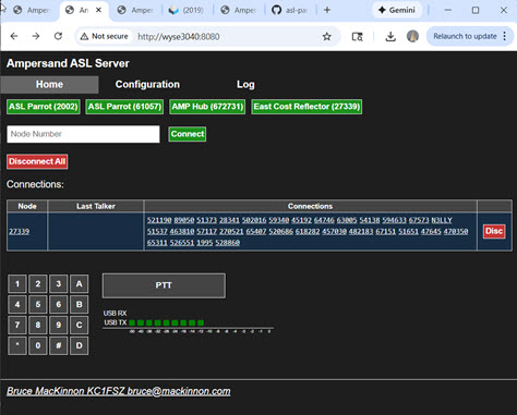
Ampersand Server User Interface
The Ampersand server runs on Linux or Windows. A browser-based user interface is provided via an integrated HTTP server.
The home tab:
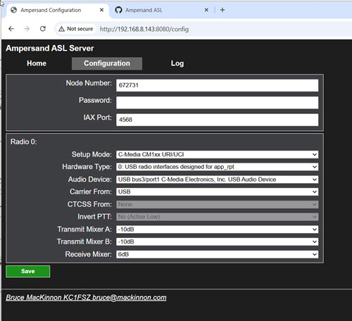
The configuration tab is shown below. There are no configuration files. The system is configured/managed using a browser, similar to the experience setting up a home router or a SIP phone.
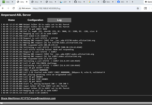
The log tab:
Conceptual Model of the Ampersand Server
(Work in process, diagram needed)
This section describes the conceptual model of the Ampersand Server. Ampersand enables integration with the AllStarLink network (abbreviated ASL). For the purposes of this description, we define ASL as the following:
- A namespace that assigns a unique identifier for each node on the ASL network.
- A robust process for issuing node numbers that tracks ownership, prevents duplicates and ensures that only licensed amateurs are allowed on the network.
- The documented IAX2 protocol, which allows ASL servers to communicate with each other across public/private IP networks.
- The AllStarLink registration service that provides:
- The ability to resolve a node number to a network address using documented APIs and/or DNS.
- A secure way to allow a node owner to update the network address of their node using documented APIs.
- The AllStarLink monitoring service which provides:
- The ability to view/query status information for any node on the ASL network using defined APIs or through a sophisticated web portal.
- The ability for nodes to periodically post their status using defined APIs.
- Some “parrots,” and other special-purpose nodes that provide the diagnostic/support capabilities necessary for a robust network.
- A community forum used to make announcements and discuss the ASL network.
- The ability to collect donations necessary to support the infrastructure for this large network.
Strictly speaking, the Asterisk PBX server is just one implementation of the IAX2 protocol, but it is not a required component of the ASL network. Any network participant who is a licensed ham, makes their donation to support the infrastructure, and follows all of the protocols described above can communicate.
The Ampersand server is a process that runs on a network-connected computer or microcontroller. A server can host one or more nodes, where the term “node” has the usual meaning on the ASL network.
Nodes are connected to one another via links. Nodes that are linked pass audio and signaling information between each other. If multiple nodes are linked to the same node, those nodes are all in conference with each other. With a few exceptions, audio transmitted into a node will be received by all other linked nodes and vice-versa.
Two nodes hosted by the same server are not necessarily linked.
The Ampersand server hosts one or more lines. A line is the medium that allows audio/signaling information to be passed into and out of a node. At the moment, there are two types of lines supported by Ampersand:
- An IAX2 line, which provides the connectivity between nodes across a network.
- A USB line, which allows a node to be connected to a USB interface (typically a radio or other audio device).
(Call) (Users) (Permanent Link)
Technical Information
This section contains various articles on different parts of the ASL system. Some of this is more detail that a normal user would need, but the goal is to encourage understanding/experimentation with the mechanics of VOIP linking system.
Audio/DSP
The Ampersand audio “core” runs at 48kHz. Audio is down/up-sampled when interfacing with links that operate at lower bandwidths.
Analysts of Existing Asterisk/app_rpt DSP
I’ve done some analysis of the Asterisk/app_rpt DSP functions which is documented here. I’ve not followed the app_rpt model in all cases, but this is very good background to have.
Audio Level Measurement in the ASL System
Please see this article for more information.
Improvements on app_rpt Resampling Filter
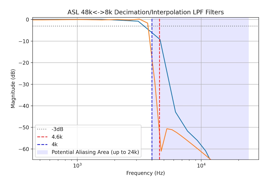
A resampling filter is needed to convert between the 8K audio used by the existing CODECs and the 48K audio used in the USB audio interfaces. This resampling requires a steep low-pass filter in both directions. The filter is applied after the up-conversion (interpolation) and before the down-conversion (decimation).
Insufficient attenuation in the stop-band of this filter leads to spectral leakage (aliasing), resulting in distortion and reduced audio quality for the user, violating standard transmission requirements. The “standard” seems to be in the range of -40dB attenuation as measured 15% up from the Nyquist rate. So in the case of the 8K filter we’ll check for aliasing suppression at 4.6kHz and for the 16K filter we’ll check at 9kHZ.
An analysis of the existing decimation/interpolation LPF filter
in app_rpt shows that the 31-tap filter currently used doesn’t
come close to the standard. See the blue curve in the figure
below. The existing attenuation is only about -9dB at 4.6kHz.
To clarify the nature of the distortion with an example, when resampling a 48K audio signal down to 8K, the image reflection is centered around the 4kHz Nyquist rate. If there is energy in the original 48K signal at 4.5kHz it will be reflected into the 8K audio as an alias signal at 3.5kHz. Obviously, this is undesirable.
I’ve implemented a steeper (and more expensive) filter in Ampersand. See the orange curve in the figure below. Anti-aliasing suppression is now about -33dB at 4.6kHz. The pass-band is also a bit wider. The filter is designed using a Kaiser window. (Particulars: cut-off is 4.2kHz, taps is 91, Kaiser beta 3.0).
I’m a nerd, but not an audio nerd so I can’t say whether this
makes a huge difference. I’m just pointing out that the current
implementation is pretty far out of spec and can be improved. I suspect
that the original app_rpt filter may have been optimized
for slower processors from the mid 2000’s. Since we’re trying to be
state-of-the-art, it’s best to upgrade these filters.
NOTES:
- Blue curve is the 31-tap FIR from
app_rpt. - Orange curve is the 91-tap FIR used in Ampersand.
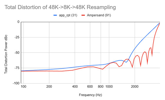
David NR9V recommended that a total distortion analysis be performed
to compare the
Ampersand resampling filter with the existing app_rpt filter. This test should
simulate the actual end-to-end path through the system. Since audio is sampled
at 48K (USB device), resampled down to 8K (since most are using the G.711 uLaw
CODEC), and then resampled back up to 48K for playback (USB device) the interesting
question is: how much distortion is introduced during those two resampling steps?
I’m not sure of the official methodology for this kind of test, but here’s what I did. The idea is to sweep across a range of frequencies. At each frequency:
- Generate a tone at a 48K sampling rate.
- Resample to 8K.
- Resample to 48K.
- Run a 1024-point FFT.
- Find the bin that represents the test tone (I’m calling this the “fundamental bin”).
- Compute the energy at the fundamental frequency.
- Compute the energy at all other frequency not including the fundamental.
- Compute the power ratio of the “other frequency power” vs. fundamental power to get the distortion in dBc.
If there was no distortion at all then no power would ever appear outside of the fundamental frequency.
Here’s the result that compares the existing app_rpt resampling process (blue) with
the revised Ampersand process (orange). Lower numbers represent lower
distortion. Here we can see
the two filters behave very similarly until about 1200kHz when the more sophisticated
filter starts to out-perform.
A few methodology notes:
- My test assumed the 8K SLIN CODEC. I did not include the small distortion effects of the G.711 uLaw CODEC since that has nothing to do with the choice of resampling filter. It would be interesting to do a test that isolates that effect as well.
- There is no window applied in the FFT.
- The sweep involves frequencies that are even multiples of the resolution bandwidth of the FFT. In this case it’s 48,000/1024 = 46.875 Hz. Without this restriction you end up with measurement distortion caused by spectral “bin spreading.”
- I remove a block of samples from the start of audio before applying the FFT to eliminate the effect of any start-up distortions caused by the FIR filter delay line.
- The noise floor of my FFT methodology was measured by performing the total distortion analysis on the original test tone before any resampling. I measured a distortion of about -91dB flat across the band. I think we can attribute that to quantization effects and other imperfections in my test setup.
16K Audio (aka “ASL-HD”)
The existing app_rpt/chan_simpleusb code appears to make the fundamental assumption that network audio is sampled at 8kHz. The USB side of the system runs at a higher rate (48K), but the captured stream is immediately down-converted to 8K. It’s possible that this restriction is inherited from the Asterisk architecture somewhere, although I doubt it because the Asterisk PBX has some 16K CODECs.
The Ampersand system avoids this limitation. The system supports a 16K audio mode that we’re calling “ASL-HD.” This may not be relevant for links between typical analog repeaters that operate with narrow audio bandwidths, but “pure digital” links (i.e. desktop-to-desktop) sound much better in 16K.
Since the Ampersand audio core runs at 48K, a decimation/interpolation low-pass filter is needed during the down/up sampling process. I’ve used a 71-tap FIR filter designed using a cut-off frequency of 7700 and a Kaiser window (beta=1).
The ideal cut-off frequency of this filter should be at 8kHz, but there is a transition band. I’ve started the transition at 7.7kHz. Here’s the transfer function of the filter used in the system:
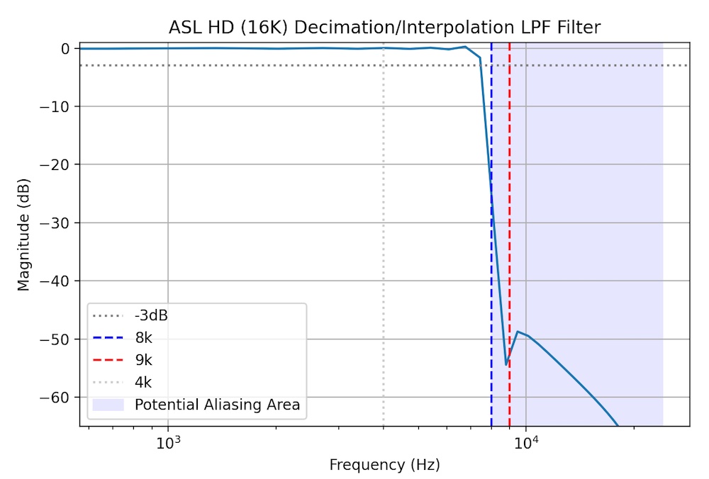
This looks decently flat in the passband, rolls off steeply, and meets the guideline of -40 to -60dB of alias attenuation starting at around 9kHz.
Ampersand’s 16K CODEC is just 16-bit linear PCM represented in little-endian format. According to the official IANA Registry for IAX there is no CODEC media code allocated for 16K PCM. However, the Wireshark dissector for IAX2 lists CODEC code 0x00008000 as 16K linear PCM. Since the IANA registry doesn’t provide an assignment for this particular code (i.e. it’s “open”) I’m assuming that’s the right one to use. (I’ll put that on the list of things to ask IANA to update in their documentation.)
Ampersand will favor 16K linear PCM whenever possible, falling back to G.711 uLaw (8K) as needed.
16K Linear “HD” Media Format Registration
An IAX2 media format needs to be defined to allow nodes to negotiate this format during call setup.
There is no official Media Format listed for 16K linear audio in the current version of the IAX2 RFC. I raised the question about the best way to represent the 16K linear media format in the IAX2 protocol on the Asterisk development forum. Someone pointed me to an older Asterisk header file that showed that media format 0x00008000 had been allocated to 16K 16-bit linear, little endian format. The same file also explicitly stated that media format 0x00000040 is for 8K linear. That shows that the IAX2 RFC is out of date. I’ve raised a request with the IANA people to have the RFC revised with this additional information. More to follow.
Jitter Buffer
The “jitter buffer” is the subject of a lot of discussion on the AllStarLink board over the years. After studying this quite a bit, I can now appreciate the challenge of making this work efficiently. I’ve been focused on adaptive algorithms that do a good job of keeping the latency through the system as short as possible. The method I’ve settled on at the moment is called “Ramjee Algorithm 1” after a paper by Ramjee, Kurose, Towsley, and Schulzrinne called “Adaptive Playout Mechanisms for Packetized Audio Applications in Wide-Area Networks”. Unfortunately, the paper is behind an IEEE paywall so I can’t link to a copy of it. This algorithm estimates the variance of the flight times of the voice packets and dynamically adjusts the size of the jitter buffer to be larger for very jittery transmissions and smaller for less jittery ones. It works pretty well at keeping the delay as short as possible.
Simple adaptive jitter buffer algorithms wait until the end of a transmission before making an adjustment to the delay. That’s usually OK, but there are times when the variance is spiking up and the adaptive algorithm would really like to extend the delay a bit to increase margin and avoid voice packet loss. Fancy VoIP systems have the ability to “slow down” a few frames of audio mid-stream to allow the delay to be extended without creating an audible gap in the conversation. This is closely related to PLC - more below.
It’s hard to tell exactly how the jitter buffer inside of Asterisk works, but I don’t think it’s using any very advanced adaptive algorithms.
Notes on EchoLink Jitter Buffer
I asked Jonathan K1RFD, the author of EchoLink, what his software does. Here’s a section of his reply:
Bruce,
I don’t recall all of the details, but here’s what I do remember:
The app looks at the sequence number of packets and is on the lookout for any gaps in the numbering, or out-of-sequence packets.
If packets which are still in the buffer are out of sequence, they are re-arranged so as to be properly consecutive.
If a gap in the numbering is detected, and the buffer is nearly empty, a packet of silence is inserted to take the place of the missing packet.
One thing to be on the lookout for is non-consecutive numbering coming from conference servers. Some conference servers might pass along the original sequence numbers from each participant, rather than generating their own new ones, and if so, this will create a big discontinuity in between transmissions. But, by that time, the buffer is probably already empty due to the pause between transmissions.
Jitter Buffer References
- A paper that talks about skew (clock speed differences) from University College, London.
- A paper: “Assessing the quality of VoIP transmission affected by playout buffer scheme”
- Paper: https://web.stanford.edu/~bgirod/pdfs/LiangMM2003.pdf
- A good/detailed reference paper written by VoCAL, a professional services firm in the VOIP space.
- Mentioned in the VOCAL reference: “The key element is the PWSOLA box (Packet-based Waveform Similarity Overlap-Add) which controls the adaptive buffer operation.”
- ALSA PCM timestamp stuff
- A journal article about statistical management of jitter
Packet Loss Concealment (PLC)
Packet Loss Concealment (PLC) algorithms are one of the tricky parts of this system. PLC is the thing that fills gaps in a transmission that result from lost or, more commonly, very late voice packets. There are a lot of research papers on this topic. At the moment Ampersand is using something called “ITU G.711 Appendix I” which is a pretty standard/simple method. From looking at the waveforms that come out of Asterisk during packet loss, I am pretty sure it uses something very similar.
It’s confusing because G.711 usually refers to the uLaw/ALaw CODECs, but G.711 Appendix I has nothing to do with these CODECs. This PLC method could be used for any CODEC. The paper is in the public domain.
The idea is to estimate the “pitch” of a short recent sample of the transmission and then generate a synthetic sound (more than just a tone) that matches that pitch during any gaps in the transmission. The G.711 algorithm “searches” for the best pitch by correlating recent history of the audio with a range of time-lagged versions of itself. Interestingly, the search range is limited to 66.66 Hz to 200 Hz, so the pitch estimation that comes out of this process is fairly low.
There are a bunch of features in this spectral interpolation algorithm that try to smooth the transitions between real speech and synthetic speech to avoid discontinuities. The result is surprisingly effective as long as the gap is small <= 60ms. And it runs well on a small microcontroller. Unsurprisingly, a lot of the cutting edge work in this space is focused on AI-driven models that predict longer passages of missing audio. It won’t be long before it can finish our sentences …
The implementation of the G.711 approach can be found in this Github repo.
PLC Using WSOLA
(Docs to follow)
Kerchunk Filtering
I love the East Coast Reflector, but there’s a fair amount of kerchunking being reflected. This is to be expected given the large number of repeaters connected on the network. I’m sure the other big networks have exactly the same problem. It would be nice to have a way to filter out this kind of activity.
I know the ASL rxondelay= helps to avoid false COS triggers and may eliminate some
quick kerchunks, but I
think that parameter
serves a different purpose. It’s basically a de-bounce on the COS line. A long
setting for rxondelay= also
has the undesirable effect of cutting off the beginning of a transmission.
Also, listening on the ECR, I suspect that a lot of the kerchunks are coming in on the various bridges to other digital modes (DMR, D-STAR, etc.) and the physical COS pin debouncing is irrelevant in those cases.
I’ve been working on a more sophisticated kerchunk filter (KF). I have a new module in the Ampersand audio pipeline that watches all of the audio frames that go by. If a transmission starts after an extended period of silence (let’s assume 1 minute, but configurable) the new audio frames are queued internally and are not passed forward in the pipeline. If the transmission ends quickly (let’s assume <2 seconds, but configurable) those queued frames are discarded under the assumption that it’s a kerchunk or some other transient. If the transmission lasts longer than 2s then it is considered to be legit and the queue starts playing out, with 2s of latency of course. Once the KF queue is drained it is bypassed and all subsequent audio is passed right through until another extended silence occurs. So basically, you are 2s behind only until that first spurt has been played out, and then no more delay. Hopefully it’s clear that none of the audio was lost, it was just delayed initially to make sure it passed the not-a-kerchunk test.
I could make this really fancy and use WSOLA to slightly speed up the playout, but I don’t think that’s necessary because the latency is reclaimed immediately on the next break in the QSO.
The 2s period was picked so that we don’t lose quick/legit transmissions. “KC1FSZ mobile, listening.”
I’ve also found that applying a voice activity detect (VAD) at the very start of a new transmission can allow an initial period of silence or near-silence to be discarded so it doesn’t count against the 2s anti-kerchunk timer. For example, if someone keyed up but remained silent for 15 seconds that should still be considered a kerchunk for our purposes.
After some experimentation with the heuristics, I’ve found the key is to make the KF aggressive after long periods of silence and then very accommodating once a new transmission becomes “trusted.”
During testing I adjusted the system so that it recorded all of the discarded audio into a single, concatenated .WAV file. This allows a quick review of what the system has classified as “kerchunk.” You can listen to one test file here that was created during 6 hours from the ECR during morning time EST. You can hear all sorts of strange sounds that were discarded. To my ear, I can only hear one thing in this test file (towards the end) that sounded like a fragment of voice audio.
The best place for this capability is in the radio input path so that it can stop kerchunks from getting into the ASL system in the first place. But what is interesting is that you can put this same module into the network audio path. So basically it can eliminate incoming network kerchunks if desired.
Hamlib Tunnel for Remote Base
(Docs to follow)
IAX2 Extensions
Voice-Level Station ID
(Docs to follow)
Performance/Speeds-And-Feeds
Here’s a link to a discussion on the ASL forum that talks about the different factors that come up with large Asterisk systems. The question of scalability will certainly come up so here are some notes that are relevant.
Capacity Critical Path
My thinking is that the most demanding case for a system like this is a large conference server. Specifically, handling the transmit path out of a large conference server. In general, it seems like there are many more listeners than talkers in the conference.
The details of the software flow are provided below, but the most important functions in the transmit path for a large conference are:
- For each 20ms frame:
- Mix the PCM audio for whatever small number of stations are talking. In Ampersand this process is happening at 48K.
- For each listener who is dialed into the conference:
- Down-sample the 48K audio to whatever rate is used by the CODEC that the listener is using. This will be 8K or 16K.
- Encode the down-sampled audio according to the CODEC being used (i.e. SLIN, G711 uLaw, etc.)
- Format a UDP packet that conforms to the IAX2 standard. In the vast majority of the cases this will be an IAX2 “mini frame,” so the formatting consists of adding 4 bytes of header information to the packet.
- Push the UDP frame into the network kernel for transmission.
If there are any other things happening, I would consider that to be overhead which should be removed if possible. All of this needs to happen every 20ms without fail, or audio quality starts to degrade.
From my measurements, it turns out that the most intensive step in the Ampersand implementation is the audio down-sampling. This is either a 6:1 or 3:1 decimation which requires a good quality low-pass filter to avoid aliasing. I’m using 71 or 91 FIR taps, depending on the target audio rate. I looked into this area and made some optimizations to make sure things were efficient. This led to a few interesting points.
- Everything can be done in fixed-point.
- There are well-known optimizations when creating decimation filters. Check out
Multirate Digital Signal Processing Crochiere/Rabiner which seems to be the
standard book in this space. Specifically:
- When decimating from 48K to 8K (or 16K), the decimation low-pass filter can skip the data output points that will be discarded in the decimation.
- Since the low-pass filter has linear phase the coefficients are symmetrical. This allows an optimization that cuts the number of multiplies in half.
- There are libraries for the ARM architecture that help leverage special math hardware. I run a lot of my stuff on a Raspberry Pi 5 which is based on the ARM Cortex-A76 processor (ARMv8-A architecture). This processor includes the NEON SIMD accelerator which makes vector math much faster. The decimation of one audio frame from 48K to 8K takes about 25 microseconds. I’ve not looked closely at x86_64 to see if there are equivalent accelerators.
There are certainly clever things that could be done to avoid duplicate down-samplings. If two listeners are using the same CODEC then we should be able to share the result of the down-sample between both of them. This gets a bit tricky when you consider that some of the connections to the conferences (i.e radios) may or may not have echo enabled, so the “mix” might be different from listener to listener. To keep things simple I’m not doing anything clever.
If we have a conference with 128 listeners, then the total time required to perform the down-sampling on a single thread is 128 x 25uS or about 4ms.
Network time needs to be considered as well. From my measurements, it takes about 1.5ms to push out 128 IAX voice frames on my Pi 5.
If we assume that each voice frame is around 320 bytes (between 160 bytes for 8K uLaw and 640 byes for 16K SLIN), and assume 128 listeners, that means that we’re pushing about 40K of data in each 20ms interval. And if we assume all of this happens 50 time per second, we end up with a network load of around 16 Mbs which seems reasonable in the modern world.
Capacity Testing (February 2026)
I recently did some testing to try to quantify the limiting factors. My test consisted of a single Ampersand hub server running in the AWS cloud with a large number of test nodes connected and listening to the conference audio at the same time.
As expected, the limiting factor is the speed of calculating and distributing conference audio to the conference listeners. If the distribution of an audio frame can’t be completed (including the network part) in <20ms the frame gets lost and audio quality degrades.
I developed a test node that will open an arbitrary number of listen-only connections simultaneously. This allows a high volume of callers to be simulated. Unfortunately, this test isn’t perfect because it doesn’t fully simulate the distribution of the clients across different networks. I partially addressed this by running my test nodes in four different AWS regions (Northern Virginia US, Ohio US, Central Canada, and Ireland).
The hub for this test ran on an AWS c6g.large instance (costs about $30/month). According to some discussion on one of the VOIP forums this instance type is frequently used to host PBX systems. It is CPU and network optimized. The instance uses an ARM Graviton2 processor that includes support for the NEON instruction for DSP acceleration (see above).
Bottom line: the breaking point is around 500 connections. I made this recording of the test so you can hear what the audio sounds like at scale. A few notes about what you’re listening to:
- The test hub was started in the AWS NorCal US region. The hub process is set to use the Linux RR (real-time) scheduler policy with a priority of 50. These are settings recommended on a VOIP/PBX forum.
- I launched four copies of my load test node, each making 125 connections to the test hub. These connections originated from Northern Virginia, Ohio, Central Canada, and Ireland. All of these connections requested the G711 ulaw CODEC.
- I launched two normal instances of the Ampersand server on my desktop in Massachusetts and connected both to the test hub, requesting the 16K HD CODEC.
- I started the audio recorder on the first of my two Windows desktop nodes.
- I commanded the hub to report its status using DTMF *70. The read-back announces 502 connections and lists off the first few connections. (NOTE: The first time I ran this test it tried to read off all 502 connections and overflowed the TTS queue - obviously that needed to be changed!)
- I commanded the hub to connect to the 61057 parrot using DTMF *361057. Here the audio gets a bit muddled because the hub’s telemetry announcement is overlapped by the parrot’s initial greeting, but at least you can hear that the mixing is working properly.
- The parrot’s network test reports a “ping time 0ms” because the parrot and the hub are both running in the same AWS region.
- After the parrot is finished talking I keyed up the Allscan UCI90 on the second of my two desktop nodes and talked into the parrot via the hub. The recording captures the audio coming back through the hub on the cross-country link. The audio sounds smooth to me.
- There are a few “bings” in the background of the recording. That is the Windows sound when you change the volume level. I was lowering the volume to limit audio feedback between my two desktop nodes. That has nothing to do with the test.
The metrics being captured show that the processing time for each audio cycle is about 12ms, so there’s not a lot of margin here. This is a single-threaded process which I think is best for this kind of timing-critical application because it leads to a simple, very predictable design.
From some preliminary testing, I’m pretty sure that the breaking point has more to with network efficiency than processing speed. Supporting 500 clients requires 25,000 UDP writes/second, all to different end-points. There are some optimizations that are needed to be able to push up to the next level, specifically I see that some of the really high-end gamers/streamers are using the sendmmsg() system call to cut down on the number of system calls required.
Minor point: the ASL protocol defines a text message “L” that sends the list of connections to all connected nodes every 10 seconds. When you have >500 nodes connected at the same time this message gets pretty big. I arbitrarily decided to cut the list short at 1500 bytes - everything above that gets lost. Maybe this will matter to someone? I doubt it.
I will be sure to fix the stats API so that is posts the comprehensive list of connections. People might care about that more.
Related note (thanks to Allan WA3WCO) - here’s a GitHub issue on a similar topic in the app_rpt code.
NOTE: This test did not work on the first try. The high volume testing uncovered a number of crashes, bugs, and other inefficiencies in my implementation. Getting these things ironed out was probably the biggest value in this experiment. There may not be much practical use for a 500-user conference hub. Maybe some day.
David NR9V has put out the 1,000 caller challenge. I will need to circle back to this testing later. :-)
CODEC Notes
G.711 (uLaw and ALaw)
Audio is sampled at 8kHz, one 160 byte frame every 20ms. Ampersand is currently only supporting the uLaw format. This is a 64kbs datastream.
G.726
This is an 8kHz CODEC that supports a variety of bitrates. The most common one, and the one that we are using for Ampersand, is the 32kbs rate. It turns out that is CODEC is the default for many HamVOIP distributions.
- Official specification is here.
- Test vectors are here.
- This application node from TI is very helpful because it points out some errors in the official specification.
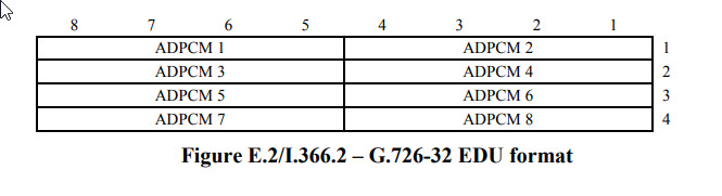
The encoder converts PCM samples into 4-bit samples. There is a packing convention required here. Ampersand/Asterisk are using the “G.726 AAL2 packing” (defined in ITU-T I.366.2, Annex E) which is a big-endian format used for ATM AAL2 transport. In AAL2, the most significant bit (MSB) of the first code word aligns with the MSB of the byte.
Here’s the picture from ITU-T I.366.2 Annex E:
I think there is some confusion in the IAX documentation. Section 2.15 of the IAX2 RFC lists media format 0x00000010 as “G.726” and format 0x00000800 as “G.726 AAL2.” However, I tried to connect to a few nodes (UK parrot 40894 and ECR 27339) using the 0x800 media format and was rejected. When I switched to format 0x10 the connection was accepted and the G.726 audio sounded fine in both directions. I’ve implemented the AAL2 variant as I understand it (big-endian packing) so I’m not sure what’s going on here. I will stick with 0x10 since the nodes I tested accepted it.
G722
Not implemented by Ampersand.
G722 Specification - Audio sampled at 14 bits 16kHz produces a 64kbit/second stream. There is no official/fixed frame size defined in the specification, but one frame every 20ms would result in 160 bytes/frame. I think the PJSIP documentation indicates that a 20ms frame rate is used in that implementation.
Repeater Logic/Timing/State Machines
This is a tedious topic that needs to be addressed in any repeater controller. There is a fairly complicated set of timers and state-machines that coordinate the flow of audio and control signals. Since some people are using their AllStar nodes as their repeater controller, the sophistication needed is more than you’d expect for a simple VOIP/ROIP application. It seems like you need to have full controller capability to be taken seriously. Certainly the AllStar people are building way more complex nodes than I ever encountered while working on EchoLink. It’s quite cool.
It also turns out that some of the features that are usually associated with fancy “professional grade” repeater systems are useful on the low-end as well. For example, SA818 radio modules seem to cut off the first part of transmissions after a long period of silence. An audio delay line in the transmit path can help to improve this experience.
It would be nice to separate the discussion of timers, repeater ID, CTCSS, delays, duplex, etc. into separate sections, but it turns out that these things are all very intertwined. I’ll work on trying to organize this clearly, but that may be difficult to do. :-)
Thanks to Patrick (N2DYI) and Gary (KK6RQ) for their review/suggestions on this stuff.
The Transmit Path
Goals
- Prevent the first part of a transmission from being clipped off, even in cases where the radio’s key-up behavior is slow (ex: SA818 modules, but maybe other radios). Try to move away from having to tell everyone to wait for a few seconds at the beginning of their transmissions to allow a transmitter to key up (this delay should be provided automatically if the hardware requires it).
- Provide a hang time at the end of a transmission to prevent excessive key up/key down.
- Provide support for a “chicken interval” at the end of a transmission during which the CTCSS/DCS tone is either turned off, phase-reversed, or changed to another arbitrary frequency in the brief interval before the transmitter is unkeyed.
- Allow the rules for CTCSS/DCS tone generation and hang times to be different depending on whether the audio being transmitted is from the conference (human-generated) or telemetry (machine-generated).
- Provide a smooth audio experience when conference audio and telemetry audio are overlapping.
- Keep audio latency to a minimum.
- Operate independently of the receive path to maintain flexibility with respect to duplex modes
Parameters
- CTCSS/DCS encoder on/off
- CTCSS/DCS frequency/code
- CTCSS break mode (chicken, reverse, secondary frequency)
- Send CTCSS/DCS during telemetry?
- Keyup interval
- Courtesy tone enabled?
- Hang interval
- Chicken interval (Time between CTCSS break and unkeying)
All intervals are in milliseconds. Any of the intervals can be set to zero to disable the relevant feature.
Transmit System Logic/State Machine
There are two audio delay lines, one for conference audio (people speaking) and one for telemetry that includes machine-generated voice prompts and CW ID. These delay lines are separated because some of the rules for dealing with these two streams are different. Courtesy tones and CTCSS/DCS tones are not considered to be telemetry in this description.
We start in the idle state.
While in the Idle State:
- The PTT signal is deasserted
- The CTCSS/DCS encoder is off.
- If conference/telemetry audio is received it is pushed onto the back of the appropriate delay line and we enter pre-transmit state.
While In Pre-Transmit State:
- The PTT signal is asserted.
- If at any time while in this state there is audio seen in the conference delay line the CTCSS/DCS encoder is turned on in normal mode.
- If at any time while in this state there is audio seen in the telemetry delay line and the “Send CTCSS/DCS During Telemetry” option is on, the CTCSS/DCS encoder is turned on in normal mode.
- Any conference/telemetry received is pushed onto the back of the appropriate delay line.
- Pre-transmit state lasts for the time defined by the keyup interval. Once this interval expires we enter transmit state.
While in Transmit State:
- The PTT signal is asserted.
- If at any time while in this state there is audio seen in the conference delay line the CTCSS/DCS encoder is turned on in normal mode.
- If at any time while in this state there is audio seen in the telemetry delay line and the “Send CTCSS/DCS During Telemetry” option is on, the CTCSS/DCS encoder is turned on in normal mode.
- Any conference/telemetry received is pushed onto the back of the appropriate delay line.
- Any audio on the conference or telemetry delay lines is popped, mixed (as needed), and sent to the radio.
- Once both delay lines are completely empty:
- If the last audio sent to the radio included any audio from the conference delay line we enter the courtesy state.
- If the last audio sent to the radio came from the telemetry delay line we jump to the chicken state. There is no need to create a courtesy tone or hang interval following machine-generated traffic.
While in Courtesy State:
- The PTT signal is asserted.
- The CTCSS/DCS encoder carries its state from the transmit state.
- The courtesy tone is enabled.
- The courtesy state lasts as long as is required to generate the courtesy tone. Once this interval expires we enter the hang state.
- Any conference/telemetry audio received is pushed onto the back of the appropriate delay line and we re-enter the transmit state. It is important to note that we bypass the pre-transmit state in this case. No further audio delay is needed since the transmitter is already keyed up.
While in Hang State:
- The PTT signal is asserted.
- The CTCSS/DCS encoder carries its state from the transmit state.
- The hang state lasts as long as the hang interval. Once this interval expires we enter the chicken state.
- Any conference/telemetry audio received is pushed onto the back of the appropriate delay line and we re-enter the transmit state. It is important to note that we bypass the pre-transmit state in this case. No further audio delay is needed since the transmitter is already keyed up.
While in Chicken State:
- The PTT signal is asserted
- The CTCSS/DCS encoder is in off/reverse/alternate frequency mode according to the configuration.
- Any conference/telemetry audio received is pushed onto the back of the appropriate delay line.
- The chicken state lasts for the chicken interval. Once this interval expires we enter the idle state.
The Receive Path
Goals
- Avoid losing the beginning part of any legit transmission.
- Avoid contributing a crash into the conference at the tail of a transmission.
- Debounce the COS/CTCSS/DCSS signals to avoid false detects.
- Provide optional kerchunk suppression to prevent short transmissions (<2 seconds) from being contributed to the conference. Note that a short transmission that closely follows other legit traffic is not considered to be a kerchunk.
- Keep latency to a minimum.
- Operate independently of the transmit path to maintain flexibility with respect to duplex modes
Configuration Parameters
- Squelch type parameter that determines whether to use carrier squelch or tone squelch.
- Debounce Interval
- Squelch Tail Interval
- Kerchunk Interval
- Idle Interval
All intervals are in milliseconds. Any of the intervals can be set to zero to disable the relevant feature.
Receive System Logic/State Machine
The system contains an audio delay line. Audio can be pushed onto the back of the delay line per the conditions below. Audio will be popped off the front of the delay line and sent to the conference whenever the audio gate is opened. If the audio gate is closed then audio just accumulates in the delay line.
The term “CTCSS/DCS signal” is used below to indicate either (a) the state of a hardware signal driven by a receiver or (b) the state of the soft decoder which is derived from the audio stream.
We start in the idle state with the audio gate closed.
While in the Idle State:
- Any audio received from the radio is ignored.
- If the COS and/or CTCSS/DCS are asserted (according to the squelch type) we enter the assessment state.
While in the Assessment State:
- Any audio received from the radio is pushed onto the back of the delay line. We don’t want to lose anything while we assess whether this is a legitimate transmission.
- The assessment state lasts for the longer of the debounce interval or the kerchunk interval. If we have been in the receive state recently (where “recently” is defined by the idle interval), the kerchunk interval is ignored in this condition and we only consider the debounce interval. We do this because the kerchunk interval is probably fairly long (a few seconds) and we don’t want to carry this much latency once a legit QSO is up and running.
- If the COS and/or CTCSS/DCS signals are deasserted (according to the squelch type) we enter the idle state and the delay line is flushed. The assumption in this case is that this was not a legit transmission and no audio was ever contributed to the conference.
- Once the assessment state has expired we open the audio gate and enter the receive state.
- Delayed audio now starts to flow into the conference.
While in the Receive State:
- Any audio received from the radio is pushed onto the back of the delay line.
- If the COS and/or CTCSS/DCS signals are deasserted (according to the squelch type) we trim audio from the back of the delay line by the equivalent of the squelch tail interval. The assumption is that the last part of any received audio just prior to the COS/CTCSS/DCS drop is a crash. For example, if the squelch tail interval was set to 200ms, 10 20ms frames of audio will be trimmed from the back of the delay line.
- After this trim has been performed we move to the drain state. Note that delayed audio is still flowing out to the conference since the gate is still opened.
While in the Drain State:
- Any audio received from the radio is ignored.
- Once the delay line is completely empty we close the audio gate and enter the idle state.
- If the COS and/or CTCSS/DCS signals are asserted (according to the squelch type) we enter the assessment state.
Duplex Behavior
(TO FOLLOW)
Software Architecture
The system is written in C++. I think this is a big step-up from C, but may still be considered a legacy language by many. C++ was originally invented at Bell Laboratories for telecom applications so it’s nice to use the language as it was originally intended. :-)
The source code for the system is developed in this set of Github repos. The main branch is production/stable. Development activity is integrated on the develop branch.
I accept PRs to the develop branch.
Software License
Ampersand is released under the GNU Public License.
Software Structure - Repos
The code is divided into a few repos:
- amp-core contains most of the code, but doesn’t build any executables. See below. Some parts of this code are able to built on a microcontroller platform.
- amp-server contains the code required to build the Ampersand Server on LINUX.
- amp-hub contains the code required to build the Ampersand Hub on LINUX. This would be used for “virtual” or cloud nodes with no connection to radio hardware.
- asl-parrot contains the code required to build the ASL parrot server (LINUX).
- amp-win contains the code required to build the Ampersand Server on Windows. (WORK IN PROCESS)
The code depends on some external/3rd-party repos that are referenced as GIT submodules.
- kc1fsz-tools-cpp. A generic C++ tools library used across many KC1FSZ projects.
- kc1fsz-sdrc A software-defined repeater controller (SDRC) project. This project pre-dates the Ampersand project.
- The ITU G711 CODEC. Contains the G711 CODEC and G711 PLC code.
- CMSIS DSP Mock Library. A “mock” (i.e. simple, not-optimized) implementation of some of the important functions defined in the ARM CMSIS DSP library to improve portability of code targeting an ARM microcontroller onto “normal” platforms.
- Craig McQueen’s COBS Implementation A nice C implementation of the Consistent Overhead Byte-Stuffing algorithm. This is used when communicating with the SDRC platform.
- An Implementation of ED25519. Used for PKI.
- A C++ HTTP Server Library. Provides a fully embedded HTTP server.
Software Structure - High Level Diagram
This is a high-level diagram of the major software components:
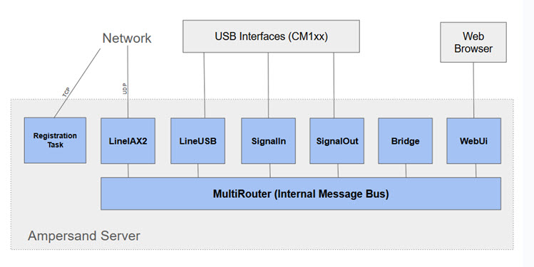
- RegistrationTask - Runs the background and performs an ASL registration (via HTTPS call) every 12 minutes.
- LineIAX2 - Implements the IAX2 protocol.
- LineUSB - Interface to the USB audio interface.
- SignalIn - Interface to the USB HID interface needed for COS/CTCSS signals. Also integrates with GPIO pins if needed.
- SignalOut - Interface to the USB HID interface needed for the PTT signal. Also integrates with GPIO pins if needed.
- Bridge - Provides audio conference capability.
- WebUi - Provides an HTTP interface for a simple browser-based user interface. There is no separate HTTP server, this uses a a C++ HTTP Server Library to avoid the need for deploying separate processes.
- MultiRouter - An internal publish/subscribe bus for routing messages between components in the server.
Software Structure - Tracing the Audio Flow
One good way to explain the structure of the Ampersand code is to describe the detailed steps involved in taking a packet of IAX audio from the network and converting it to USB sound.
Keep in mind that each frame contains exactly 20ms of audio, so this entire flow happens about 50 time per second, regardless of the audio sampling rate.
Everything described below happens on a single processing thread under
the control of the EventLoop class.
Phase 0 - Happening Continuously
- The main processing thread is looping in a class called
EventLoop. You can see that towards the bottom ofmain()in themain.cppfile of the amp-server project. - The
EventLoopis keeping track of timers and monitoring for activity on file descriptors.
Phase 1 - Driven By IAX2 Packet Arrival
- Everything starts with UDP (IAX2) frames on the network.
LineIAX2class is listening on a UDP socket and will receive the voice frame. At startupLineIAX2has toldEventLoopabout the socket file descriptors it cares about, so when UDP data arrivesEventLoopwill dispatch theLineIAX2::run2()function. - Function
LineIAX2::_processInboundIAXData()is where the actual call to the socketrecvfrom()happens. Keep in mind that the arrival of these frames is asynchronous and may not be perfectly spaced. - The frame is examined to determine which call it belongs to. The frame is
forwarded to the correct instance of the
LineIAX2::Callclass for call-level processing. SeeLineIAX2::_processFullFrameInCall()orLineIAX2::_processMiniFrame()depending on whether the voice frame is full or mini. - The voice frame is made into an instance of the
Messageclass and is then put onto an internal message-passing bus. The bus is implemented by theMultiRouterclass. - The server contains a conference bridge which is the central core of the system.
This is where all audio is collected, combined, and re-distributed. The conference bridge is implemented by the
Bridgeclass. - The
MultiRouterforwards theMessagecontaining the voice frame to the conference bridge (see theBridge::consume()method). - The
Bridgelooks at theMessageand finds the appropriate instance of theBridgeCallclass. There is aBridgeCallfor each active participant in the conference, including the physical radios. SeeBridgeCall::consume(). - The
BridgeCallhas a component responsible for call-level inbound audio calledBridgeIn. TheMessageis passed to theBridgeInclass (seeBridgeIn::consume()). BridgeInimplements a pipeline. First, theMessageis passed to the jitter buffer implemented by theSequencingBufferStdclass. SeeSequencingBufferStd::consume().- The
Messageis stored in the jitter buffer until it is selected for playout in phase 2a. - That’s the end of phase 1. The system becomes idle at this point.
Phase 2a - Driven by the 20ms Audio Clock
- The
EventLoopis maintaining a set of timers. - Every 20ms the
Bridgeclass wakes up and tries to produce an audio frame for each conference participant. - Here we pick up with the next steps on the
BridgeInaudio pipeline. - The first step is to prompt the jitter buffers in each
BridgeCallto play out a frame. TheSequencingBufferStdwakes up and decides which is the nextMessageto be played based onMessagetimestamps, latency calculations, etc. SeeSequencingBufferStd::playOut()for this complicated process. - Once the
Messageemerges from the jitter buffer it is transcoded from its network encoding to a 16-bit signed PCM format of the same sample rate. So, for example, if the network encoding is G.711 it is transcoded to 16-bit PCM at 8kHz. - The PCM audio is then passed through the packet-loss concealment (PLC) step which
is implemented by the
Plcclass from theitu-g711-codecrepo. This is where interpolation is performed to smooth over any gaps in the audio stream. - The output of the PLC step is still 16-bit PCM audio. The next step is to resample that audio up to 48K.
- The 48K audio is packaged into a new
Messageinstance and is passed into the Kerchunk Filter (KF) implemented by theKerchunkFilterclass (seeKerchunkFilter::consume()). Here some analysis/filtering is performed to decide if the audio frame should be dropped, or at least delayed to reduce the impact of spurious kerchunks. - One the KF is complete the
Messagecontaining the 48K audio frame is staged at the end of theBridgeInpipeline. - That’s the end of phase 2a.
Phase 2b - Driven by the 20ms Audio Clock
- Every 20ms the
Bridgeclass wakes up and produces a 48K audio frame that represent the “mix” of all conference participants who where talking during that 20ms tick. - The
Bridgeloops through all of the activeBridgeCalls, determines which have audio to contribute, and callsBridgeCall::extractInputAudio()for each to pull the staged frame for the current tick, scaling appropriately based on the number of active speakers. - The
Bridgethen provides the mixed audio for that tick to each conference participant by callingBridgeCall::setOutputAudio(). - The
BridgeCallhas a component responsible for handling output audio pipeline calledBridgeOut.TheBridgeCallpasses the mixed frame to theBridgeOutusingBridgeOut::consume(). BridgeOutresamples the 48K audio to the rate required to support the CODEC used by the output conference participant. For example, if the participant is using the 16K SLIN CODEC the audio frame is resampled from 48K down to 16K.BridgeOutthen transcodes the PCM audio into the CODEC format used by the conference participant. This audio is packaged into a new instance of theMessageclass.- The encoded
Messageaudio is passed into the message busMultiRouter.SeeMultiRouter::consume(). - This is the end of phase 2b.
Phase 2c - Driven by the 20ms Audio Clock
(The description of this phase is unique to the USB radio interface.)
- The
MultiRouterexamines theMessagecreated in phase 2b and dispatches it to the appropriate listener. This will be an instance of theLineUSBclass in this case. SeeLineUSB::consume(). LineUSBmakes heavy use of its base classLineRadiosince much of the code related to radio interfaces can be shared between USB and non-USB cases. TheMessageis passed toLineRadio::consumefor processing.LineRadio::consume()does some analysis of the audio frame to keep statistical information (peak, power levels, etc.) up to date. It then calls back down toLineUSB::_playPCM48k()LineUSB::_playPCM48k()accumulates the 20ms audio frame into a circular buffer that can hold about 60ms of audio. This buffer is calledLineUSB::_playAccumulator. Some margin is required here because the USB sound driver/hardware is operating asynchronously from the rest of the system and may get slightly ahead/behind based on its own internal timing.- This ends phase 2c.
Phase 3 - Driven by the Availability of USB Play Buffer Space
(The description of this phase is unique to the USB radio interface.)
- The
EventLoopobject is constantly checking to see if the USB play buffer is reporting that it has room. If so, the steps in this phase are executed. The exact timing of this process is not known because the USB hardware interface operates somewhat asynchronously from the rest of this system. LineUSB::_playIfPossible()is called. The contents of theLineUSB::_playAccumulatorare pushed into the USB play buffer. A return code is examined to determine how much audio was actually accepted. The amount of audio that will be accepted is not known in advance because the USB hardware is operating asynchronously. Whatever audio is accepted into the USB play buffer is removed from theLineUSB::_playAccumulator.- This ends phase 3. The audio frame should be heard.
A Few Notes on Project Software Philosophy
This is a C++ project. However, you’ll note that there are no deep/complex inheritance hierarchies. Also, the use of templates/meta-programming is kept to a minimum. Abstract interfaces (GoF Facade Pattern) are used as much as possible.
Linkages between the major components is kept as loose as possible. This is particularly relevant in an application like this that deals heavily with networking. Most of the interaction between major components of the AMP Server are achieved through an asynchronous Message-passing interface.
The use of multi-threading is kept to an absolute minimum. There are two reasons for this. First, I want to be able to run large parts of this code (not 100%) on bare-metal micro-controllers that lack a thread primitive. But more importantly, I have spent too many years of my life debugging complex (and often non-reproducible) bugs related to concurrency errors. The best advice I’ve seen to improve the reliability of multi-threaded architectures is: just don’t do it!
Being reasonable, there are some places where threads are unavoidable, or at least the work-around is very difficult. In this system, the only interaction between threads should be via Message-passing through a thread-safe queue. Anything else is asking for problems that I don’t want to spend time debugging. Given this philosophy, there should be no mutexes or other synchronization objects in most of the code.
The code below provide a good example of my general concern:
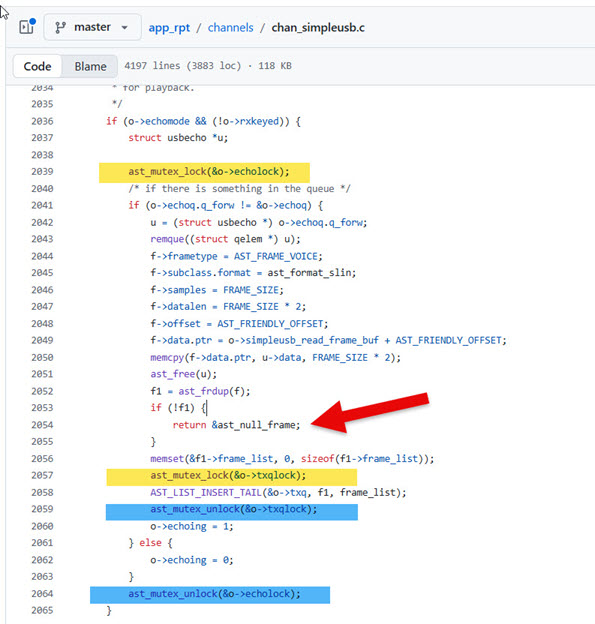
Notice a few things:
- There are some things in this function that need to happen under lock and some things that don’t. All developers need to be on the same page, which can be hard in a distributed/open-source team. One missed lock and you might have a strange bug.
- Certain locks cover certain resources. Depending on how many shared resources there are this could be very complicated to keep track of.
- It’s very easy to create a situation like the one shown on line 2054 of this function. Notice that a lock is acquired at line 2039 but the function possibly returns at line 2054 without releasing the lock. Is this a bug?
NOTE: I’m not being critical of app_rpt or chan_simpleusb here, this is just the first
file that came up when I started searching for calls to the lock/unlock functions.
On a similar note, the use of dynamic memory allocation is kept to a minimum. First, I want to be able to run this code on bare-metal micro-controllers that lack dynamic memory. But more importantly, I have spent too many years of my life debugging complex (and often non-reproducible) bugs related to memory errors.
There are certain parts of the system that do not run on the microcontroller platform and those parts will use things like std::string, std::vector, that use dynamic memory internally. But much of the core system does everything on the stack.
IAX2/ASL Network Protocol Notes
One of the hardest part of this project is understanding the details of the IAX2 Protocol and, importantly, how it is interpreted by Asterisk.
There are also some ASL-specific HTTP protocols used for various administrative tasks. These are not well documented.
Lastly, Asterisk supports an administrative protocol called AMI. This is a TCP protocol that can be used to send commands and status requests to an Asterisk server. (NOTE: I don’t plan to implement this part of the system, but the background is helpful.)
This section contains my notes on these various protocols.
Network Information
IAX2 usually runs on UDP port 4569. This is the only port that needs to be open from the outside. It is possible to change this to an arbitrary port number during server setup and the various DNS discovery protocols support alternate port numbers.
AMI usually runs on TCP port 5038.
ASL Node Registration
The ASL system provides a central database that maps an AllStar node number to an IP address/port. This is only relevant for “public” nodes. Any public AllStar node that wants to be reachable must register itself on an ongoing basis.
There are two protocols that can be used for registration:
- The HTTP endpoint, documented here.
- An IAX registration (REGREQ, REGAUTH, REGACK). It seems like the ASL3 Establishment is actively discouraging the use of this method so I’ve not looked at it very closely.
The HTTP registration protocol works as follows.
A JSON message is sent to the AllStarLink registry when a node starts up and every few minutes on an ongoing basis. This registration allows the network to know the IP address that the node is running on.
The format of this JSON message doesn’t appear to be directly documented, but it can be determined from looking at the source code. Here’s the JSON message (the important part):
{
    "port": 4569,
    "data": {
        "nodes": {
            "61057": {
                "node": "61057",
                "passwd": "xxxxxx",
                "remote": 0
            }
        }
    }
}
I’m not sure what the significance of the port number is and I have a feeling that it’s not used. When you setup an ASL server using the ASL portal you specify the IAX port number and I’m pretty sure this is what is used. (If anyone knows differently please let me know.)
Here’s an example of a command that will send the properly formatted message:
curl -X POST "register.allstarlink.org" \
     -H "Content-Type: application/json" \
     -d '{
    "port": 7777,
    "data": {
        "nodes": {
            "61057": {
                "node": "61057",
                "passwd": "xxxxxx",
                "remote": 0
            }
        }
    }
}
' \
     --trace allstarlink.log
The responses look like this:
Good:
{"ipaddr":"108.20.174.63","port":4569,"refresh":179,"data":["61057 successfully registered @108.20.174.63:4569."]}
Bad:
{"ipaddr":"108.20.174.63","port":4569,"refresh":179,"data":["61057 failed authentication. Please check your password and node number."]}
NOTE: Both return HTTP code of 200
ASL Node Query
This is an HTTP query endpoint that can be sent to the ASL infrastructure to get status information on a specific node. This is not needed for normal operation. I’m not using this endpoint at the moment, but I know other applications do.
The URL has this format:
http://stats.allstarlink.org/api/stats/61057
A GET will return a JSON message like this:
{
    "stats":{
        "id":31620,
        "node":61057,
        "data": {
            "apprptuptime":"409053",
            "totalexecdcommands":"0",
            "totalkeyups":"0",
            "totaltxtime":"0",
            "apprptvers":"3.5.5",
            "timeouts":"0",
            "links":[],
            "keyed":false,
            "time":"1761566153",
            "seqno":"13638",
            "nodes":null,
            "totalkerchunks":"0",
            "keytime":"409063",
            "linkedNodes":[]
        },
        "created_at":"2024-04-03T15:06:30.000000Z",
        "updated_at":"2025-10-27T11:55:53.000000Z",
        "user_node":{
            "Node_ID":74479,
            "User_ID":"KC1FSZ",
            "Status":"Active",
            "name":"61057",
            "ipaddr":"108.20.174.63",
            "port":4569,
            "regseconds":1761438377,
            "iptime":"2025-10-07 19:49:05",
            "node_frequency":"",
            "node_tone":"",
            "node_remotebase":false,
            "node_freqagile":"0",
            "callsign":"KC1FSZ",
            "access_reverseautopatch":"0",
            "access_telephoneportal":"1",
            "access_webtransceiver":"1",
            "access_functionlist":"0",
            "is_nnx":"No",
            "server":{
                "Server_ID":44296,
                "User_ID":"KC1FSZ",
                "Server_Name":"microlink-1",
                "Affiliation":"",
                "SiteName":"",
                "Logitude":"-71.29633",
                "Latitude":"42.290464",
                "Location":"Wellesley\/MA",
                "TimeZone":null,
                "udpport":4569,
                "proxy_ip":null
            }
        }
    },
    "node":{
        "Node_ID":74479,
        "User_ID":"KC1FSZ",
        "Status":"Active",
        "name":"61057",
        "ipaddr":"108.20.174.63",
        "port":4569,
        "regseconds":1761564172,
        "iptime":"2025-10-07 19:49:05",
        "node_frequency":"",
        "node_tone":"",
        "node_remotebase":false,
        "node_freqagile":"0",
        "callsign":"KC1FSZ",
        "access_reverseautopatch":"0",
        "access_telephoneportal":"1",
        "access_webtransceiver":"1",
        "access_functionlist":"0",
        "is_nnx":"No",
        "server":{
            "Server_ID":44296,
            "User_ID":"KC1FSZ",
            "Server_Name":"microlink-1",
            "Affiliation":"",
            "SiteName":"",
            "Logitude":"-71.29633",
            "Latitude":"42.290464",
            "Location":"Wellesley\/MA",
            "TimeZone":null,
            "udpport":4569,
            "proxy_ip":null
        }
    },
    "keyups":[],
    "time":1.2359619140625
}
Downloading the ASL Node Database
This endpoint will return a large file with the registration status of all nodes on the network. This method of routing/validating is discouraged:
https://snodes.allstarlink.org/gennodes.php
ASL Statistics Posting
Format of statistic post can be seen here:
[2025-10-30 23:46:26.892] WARNING[26258] app_rpt.c: statpost to URL 'http://stats.allstarlink.org/uhandler?node=644441&time=1761893052&seqno=6&nodes=T559820&apprptvers=3.6.2&apprptuptime=109&totalkerchunks=0&totalkeyups=1&totaltxtime=19&timeouts=0&totalexecdcommands=0&keyed=0&keytime=119' failed with error: Failed to connect to stats.allstarlink.org port 80 after 134860 ms: Could not connect to server
I’ve found that the URL should have a .php on the end:
http://stats.allstarlink.org/uhandler.php
If there are multiple nodes running from the same apparent IP address posting stats then it is likely that only one will succeed. The others get a 401 Unauthorized.
Other Intel on ASL Registration/Stats
A question sent to Jason N8EI:
Hi Jason: A few questions about registration/stats. If there are docs, feel free to point me instead of typing. There are times when both the Philadelphia Hub and the East Coast Reflector reject my connections. I get the feeling that (a) my node isn’t “100% registered” all the time and (b) those two hubs are using the same logic to validate me. I am sending a re-registration every two minutes and I’m not sending any stats (yet). My node isn’t running at all times (yet). Do I need to be sending stats to be fully visible on the network and accepted by these hubs? The Cloudflare thing made me aware that some nodes are doing a file download to get the node directory. I’m not doing that, I’m 100% DNS. How often does the download happen? Is it possible that some nodes are missing me because I am not up 100% of the time. Ideally, how often should I register and how often should I send stats?
Jason’s response:
For #1, if you’re talking about the statpost in app_rpt, that has no bearing on your registration stats or, in the default case, being authenticated to another node.
For #2, the file is only being updated once every 5 minutes. So if you come online after being offline for 10 minutes, then there’s a maximum of 300 seconds + whatever randomization skew there is until the the next download. The default cycle time on ASL3 was 2 minutes, now it’s 5. If they’re using something older or custom, it could be more or less aggressive on the download. 5:04
For #3, you cannot re-authenticate more than once every 120 seconds with a recommendation of 180 seconds. We actually will HTTP 429 a registration attempt that is too soon. 5:04 Oh, as a #2A, DNS is refreshed every ~60 seconds. 5:04 As in the job runs once every 60 seconds and takes anywhere between 10-30 seconds depending on how much change there is. 5:06 PM On #3, what stats frequency should I run with? Jason N8EI 5:06 PM
180s
Determining the IP Address of a Public Node
The preferred way to determine the IPv4 address/port of an AllStar node is using DNS. The ASL3 infrastructure is keeping the nodes.allstarlink.org domain up to date with the most-recently registered address of each active public node. This is a very elegant solution.
Two DNS queries are needed. The first DNS query is of type SRV (Server Selection). The name has the format:
_iax._udp.NNNNNN.nodes.allstarlink.org
where NNNNNN is the node name/number of the target node.
(A lot of what follows is generic DNS protocol stuff and is not ASL-specific. I’ve documented it for my own information.)
The SRV request is described in RFC 2782.
Here’s a good handout that provides the basics of the DNS packet format.
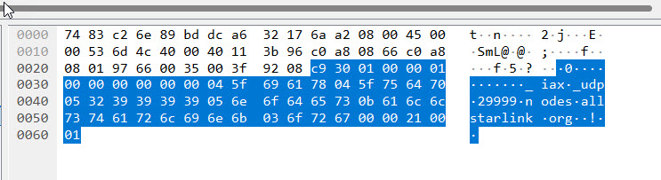
The DNS query is a UDP packet set to the server on port 53. An example of a query packet is here:
Packet analysis for reference/education:
Header
- ID=0xc930
- QR=0 (query)
- OPCODE=0, AA=0, TC=0, RD=0, RA=0, Z=0, RCODE=0
- QDCOUNT=1
Body (Question 1)
- QNAME
- QTYPE=0x0021 (decimal 33) means SRV query
- QCLASS=0x0001 internet
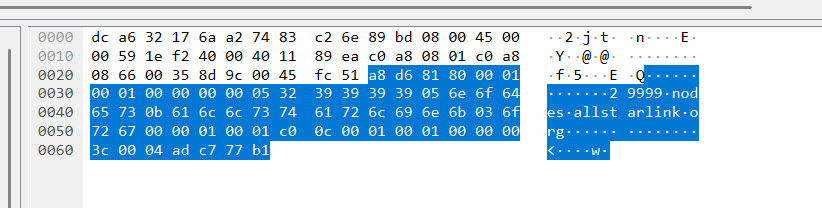
The DNS response contains the service host name (29999.nodes.allstarlink.org) and the port number (4569).
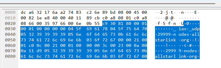
Header
- ID=0xc930
- QR=1 (query)
- OPCODE=0, AA=0, TC=0, RD=0, RA=1, Z=0, RCODE=0
- QDCOUNT=1, ANCOUNT=1
Body (Question 1)
- Domain name
- QTYPE=0x0021 (decimal 33) means SRV query
- QCLASS=0x0000 internet
Body (Answer 1)
- Compressed domain name (0xc00c)
- TYPE=0x0021 (decimal 33) means SRV query
- CLASS=0x0001 internet
- TTL=0x0000 0x003c
- RDLENGTH=0x0023 (35)
- (The SRV record with PRI, WEIGHT, PORT, HOSTNAME)
The second DNS query is of type A (Host Address). The service host name returned by the previous DNS query is sent in this query. An example is shown here:
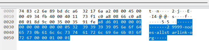
The response contains the IP address:
After this sequence is complete the IP address and port number can be used to contact the target node.
An Alternate Authentication Mechanism: Web Transceiver
There is another legacy authentication scheme call “Web Transceiver” that is used by some nodes on the network. This mode is used by DVSwitch mobile and SharkRF M1KE, but likely others. This page from the AllStarLink documentation gives some more information about the apps involved.
Looking at that app_rpt code, it appears that users who authenticate using the
WT method have limited control capabilities on the target node.
The WT authentication protocol isn’t explicitly documented anywhere that I can find, but I think it goes something like this:
- A caller first contacts an API endpoint at register.allstarink.org and authenticates. (Need to find out the exact URL format and protocol here).
- If the authentication succeeds, AllStarLink provides a temporary token to the caller.
-
The caller creates a NEW message to initiate the connection to the target node. The USERNAME (0x06) information element must contain the string
allstar-public. The caller also must provide the token issued by the registration API. Judging from the extensions.conf file, I’m pretty sure this token gets placed into the CALLING NAME (0x04) information element of the NEW message. This is the relevant configuration statement:exten => s,n,Set(RESP=${CURL(https://register.allstarlink.org/cgi-bin/authwebphone.pl?${CALLERID(name)})}) -
The target node takes the token from the NEW message and calls a different AllStarLink API (HTTP GET) using this URL format:
https://register.allstarlink.org/cgi-bin/authwebphone.pl?YOURTOKENHERE - AllStarLink checks the token for validity and returns a response that has Content-Type “text/html; charset=UTF-8.” However, the response content is just a line of plain, newline terminated text. Looking at an example extensions.conf file, it appears that there are two possible results.
This is given back for a token that is not recognized:
???
This is the positive response:
OHYES
- If the target node receives a positive OHYES response then the call is accepted.
For any of this to work the target node must be configured in the ASL portal. Select yes on the “Allow WebTransceiver/RepeaterPhone/DVSwitch access?” option.
IAX2 Audio Notes
The audio sample rate is 8kHz. Block size is 160. So each block represents 20ms of audio.
Notes on Initial Handshake
After an outgoing call is accepted by the remote server there are a few important (but somewhat hidden) handshakes that are needed. I’m not sure what all of these mean, but if you don’t follow the handshake the connection will be dropped.
The server will send a text frame that looks like this:
!NEWKEY!
The caller should respond with an identical text frame. Please note that these text frames include the null termination character.
Then the caller should sent three other text frame:
T nnnnn COMPLETE
L<space>
T nnnnn CONNECTED,nnnnn,mmmmm
Where nnnnn=local node number and mmmmm=remote (called) node number
Ongoing Handshake
There are requirements in order to keep a connection up. I’ve seen remote Asterisk servers terminate my connection if I’m not doing all of these things:
- When a PING is received, generate a PONG
- When a LAGRQ is received, generate a LAGRP
- Every 10 seconds send a PING
-
Every 10 seconds send a text record with this format:
L n0,n1,n2,...
where n0,n1,n2 are the node numbers of any nodes that are connected.
IAX2 Message Flow Examples
Call from AllStarLink Telephone Portal
A network capture was made of a node receiving a call from the AllStarLink Telephone Portal. In WireShark it looks like this:
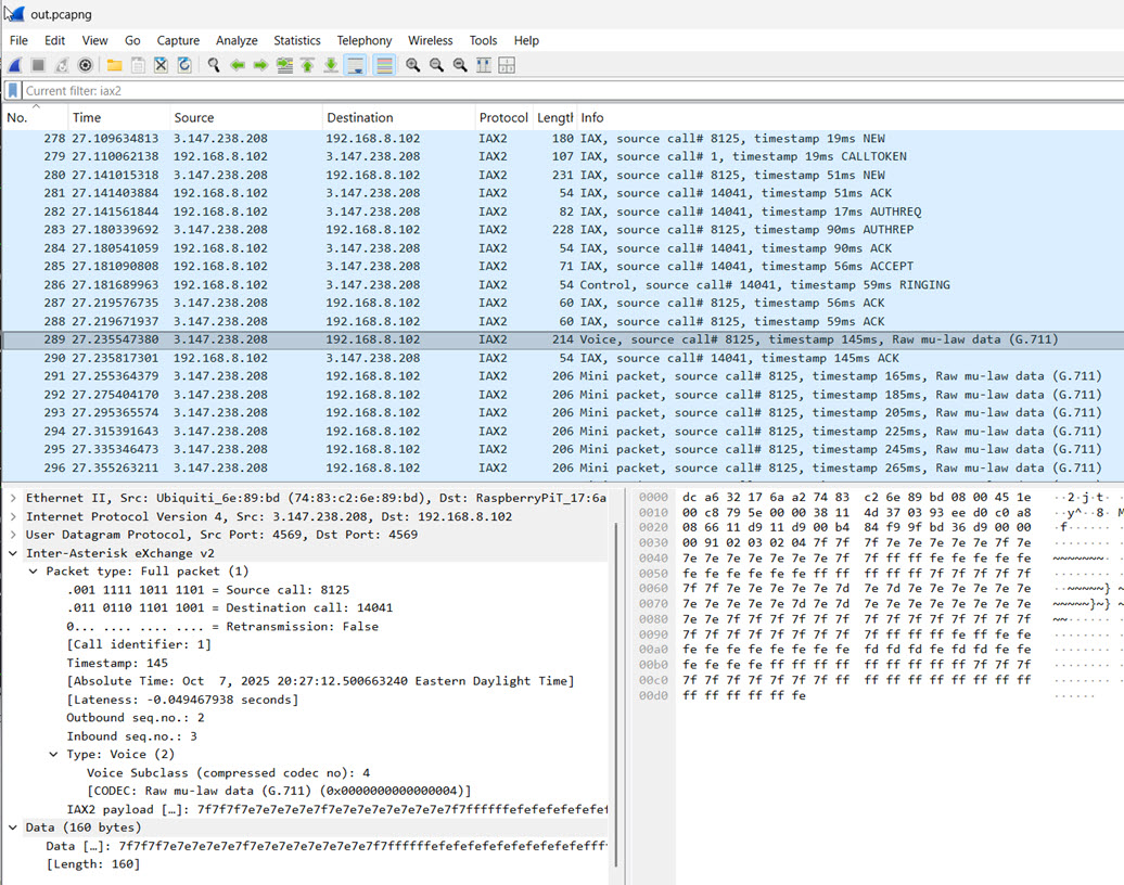
- (From Caller) Full Packet, Type=Control(4), Subclass=NEW
- (To Caller) Full Packet, Type=Control(4), Subclass=CALLTOKEN
- (From Caller) Full Packet, Type=Control(4), Subclass=NEW
- (To Caller) ACK
- (To Caller) AUTHREQ
- (From Caller) AUTHREP
- (To Caller) ACK
- (To Caller) ACCEPT
- (To Caller) Full Packet, Type=Control(4), Subclass=RINGING
- (From Caller) Full Packet, Type=IAX(6), Sublcass=ACK
- (From Caller) Full Packet, Type=IAX(6), Sublcass=ACK
- (From Caller) Full Packet, Type=Voice(2)
- (To Caller) Type=IAX(6), Sublcass=ACK(4)
- (From Caller) Mini voice packet
- (From Caller) Mini voice packet
- …
- (To Caller) Full Packet, Type=Control(4), Subclass=ANSWER
- (To Caller) Full Packet, Type=Control(4), Subclass=Stop Sounds
Call From Another ASL Node
I connected to node 29999 using the telephone portal and pressed *361057 to request a connection to my 61057 node.
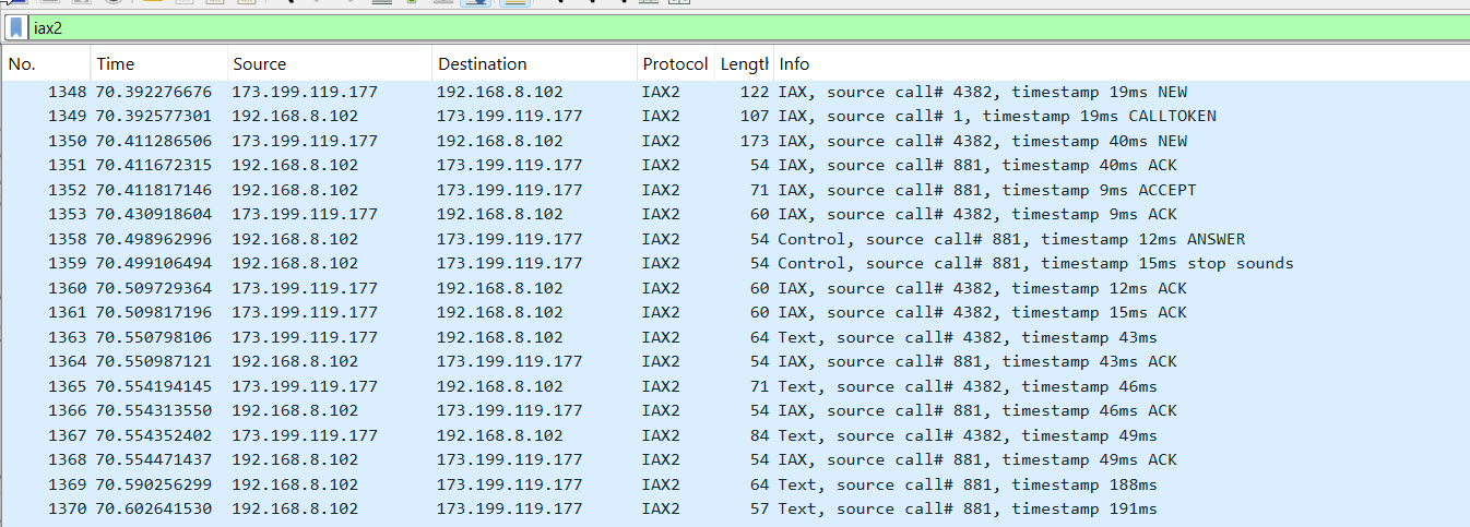
Notes:
- The usual CALLTOKEN challenge is used on the first NEW.
- The second NEW contains
- An IE with the username (6) of “radio”
- An IE with the desired CODEC
- There is no AUTHREQ/AUTHREP challenge. It appears that the connection from the remote note is unauthenticated.
- No RINGING phase. The ANSWER/stop sounds is sent immediately after the ACCEPT.
- At the very start of the call we received these TEXT packet:
- !NEWKEY!
- T 29999 COMPLETE
- T 29999 CONNECTED,29999,61057
- For more information about the TEXT protocol see: https://wiki.allstarlink.org/wiki/IAX_Text_Protocol
- The “T” messages are telemetry. See: https://allstarlink.github.io/adv-topics/telemetry/. One important thing is that it is up to the receiving node to decide what to do with these messages (for example, announce them). One of the documents mentions that a T STATUS message is sent in response to a *70 DTMF command, which makes me wonder whether the voicing of this information is completely local?
- Per documentation “There are several messages being exchanged that alter the behavior of the app_rpt application. It’s unclear as to their purpose … !NEWKEY! is meant to be some sort of handshake. When a party receives this command it should send it back.”
- Immediately after receiving those TEXT packets, the following was sent, which
is consistent with the above comment in the docs:
- !NEWKEY!
-
There are some TEXT packets exchanged every 10 seconds. It looks like a text packet with “L” is being sent every ~10 seconds. And from 29999 we get this every ~10 seconds:
L R1010,TKC1FSZ-P,T29283,T48335,T29285,T1951,T29284,T49999,T1980,T1950,R1020
which is the list of notes currently connected. Per documentation “Sent periodically by a node to broadcast all node linked to it.”
- On remote-initiated disconnect a TEXT message is received: !DISCONNECT!
- Immediately after the !DISCONNECT! is received a HANGUP is sent from local->remote.
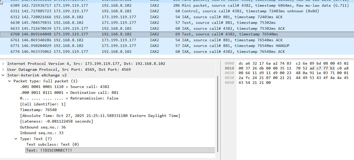
Call Out To Parrot (55553)
Initial NEW message uses CODEC Negotiation (0x2d) of “DGC.”
Sequence Number Notes
- When a NEW is received, reset the inbound inbound_expected_seq to 1 (i.e next message).
- When a NEW is received, reset the outbound_seq to 1.
- When sending a frame, set the ISeqno field to inbound_expected_seq.
- When sending any frame send outbound_seq in the OSeqno field. After sending a frame that is not an ACK increment outbound_seq field.
- When a full frame is received, check the OSeqno field vs the expected value and increment the inbound_expected_seq.
IAX2 Message Format/Semantics
NEW
Used to initiate a call. This actually comes in twice, once at the very beginning and once after a CALLTOKEN challenge is issued.
Here’s an example of the NEW message from the Telephone Portal after the CALLTOKEN challenge:
    0000 | 85 67 00 00 00 00 00 34  00 00 06 01 0b 02 00 02  ·g·····4 ········
    0010 | 01 06 33 36 31 30 35 37  2d 01 44 02 0a 39 39 39  ··361057 -·D··999
    0020 | 33 37 31 32 34 34 34 26  01 00 27 01 00 28 02 00  3712444& ··'··(··
    0030 | 00 39 04 00 00 00 00 04  06 4b 43 31 46 53 5a 0a  ·9······ ·KC1FSZ·
    0040 | 02 65 6e 1c 0a 35 30 39  32 35 35 37 38 32 37 06  ·en··509 2557827·
    0050 | 0b 61 6c 6c 73 74 61 72  2d 73 79 73 09 04 00 00  ·allstar -sys····
    0060 | 00 04 38 09 00 00 00 00  00 00 00 00 04 08 04 00  ··8····· ········
    0070 | 00 00 04 37 09 00 00 00  00 00 00 00 00 04 0c 02  ···7···· ········
    0080 | 00 02 1f 04 33 61 99 c9  36 33 31 37 35 39 38 38  ····3a·· 63175988
    0090 | 33 32 33 32 3f 65 34 62  39 30 31 37 65 31 30 32  3232?e4b 9017e102
    00A0 | 63 31 66 38 33 31 65 36  64 62 36 61 62 31 62 63  c1f831e6 db6ab1bc
    00B0 | 38 35 65 62 63 65 31 65  61 32 34 30 65           85ebce1e a240e
Name of caller (4) = KC1FSZ Calling number (2) = My mobile number
CALLTOKEN
Used to respond to an initial NEW request. Tells the the originator that a call token will be required in the NEW retry.
For unknown reasons, I observe the retransmission flag is True for an incoming CALLTOKEN message (from 55553).
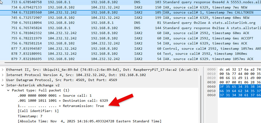
Voice Packet (Full)
G.711 μ-law payload contains the actual 8-bit μ-law encoded audio samples. The size of this payload depends on the packetization interval. 20ms of audio at 8kHz a sampling rate is 160 bytes.
Voice Packet (Mini)
At least one full voice packet must be sent before a mini packet is allowed.
A full voice packet is required when 16-bit timestamp of the mini packet wraps around to zero.
VNAK
This message is used to pro-actively request retransmission of missing messages. The name notwithstanding, it seems to be used for any type of missing messages - not just voice.
What I have observed is that when an Asterisk server is missing a message from the sequence it will wait about 8 seconds and then start sending VNAK messages fairly aggressively, perhaps one every second until the gap is resolve.
AUTHREQ
Sent from the server to the client to request authentication. Contains a 9-digit challenge, which is a random number.
AUTHREP
Send from the client to the server in response to an AUTHREQ.
Contains the RSA signature for the server’s challenge. This is Base-64 encoded. The signature will be validated by the server using a public RSA key. Digest hash is SHA1.
Sample code to illustrate the mechanics:
"""
This is a demonstration of the challenge validation process
used by AllStarLink (IAX2).

Copyright (C) 2025, Bruce MacKinnon KC1FSZ
"""
import base64
from cryptography.hazmat.primitives import hashes
from cryptography.hazmat.primitives.asymmetric import padding
from cryptography.hazmat.primitives.asymmetric import rsa
from cryptography.hazmat.primitives import serialization
from cryptography.exceptions import InvalidSignature

"""
From RFC-5456, Section 8.6.16:

The purpose of the RSA RESULT information element is to offer an RSA
response to an authentication CHALLENGE.  It carries the UTF-8-
encoded challenge result.  The result is computed as follows: first,
compute the SHA1 digest [RFC3174] of the challenge string and second,
RSA sign the SHA1 digest using the private RSA key as specified in
PKCS #1 v2.0 [PKCS].  The RSA keys are stored locally.

Upon receiving an RSA RESULT information element, its value must be
verified with the sender's public key to match the SHA1 digest
[RFC3174] of the challenge string.
"""

# The RSA public key is provided in the ASL3 installation. On the Pi
# appliance distribution it is located at:
#   /usr/share/asterisk/keys/allstar.pub
# The public key is in PEM format:
public_key_pem = "-----BEGIN PUBLIC KEY-----\n\
MIGfMA0GCSqGSIb3DQEBAQUAA4GNADCBiQKBgQCu3h0BZQQ+s5kNM64gKxZ5PCpQ\n\
9BVzhl+PWVYXbEtozlJVVs1BHpw90GsgScRoHh4E76JuDYjEdCTuAwg1YkHdrPfm\n\
BUjdw8Vh6wPFmf3ozR6iDFcps4/+RkCUb+uc9v0BqZIzyIdpFC6dZnJuG5Prp7gJ\n\
hUaYIFwQxTB3v1h+1QIDAQAB\n\
-----END PUBLIC KEY-----\n"
public_key = serialization.load_pem_public_key(public_key_pem.encode("utf-8"))

# The RSA challenge string is a 9-digit number created randomly by
# the server creating the AUTHREQ message. Here is an example that
# was captured from the network during an actual connection:
rsa_challenge = "570639908"

# The RSA signature is created by the client attempting to connect.
# This is created using the client's private key. The signature
# is sent back in the AUTHREP message. Here is an example that
# was captured from the network during an actual connection:
rsa_challenge_result_base64 = "ZanWw1+Wx5TWWX6g4890bmnflMgk8ZyyRdjINenNmzq3eYWfPMpcfMFIrHfX0gxOzGeNflcbOqr1m6GMnCoE92h+fMlIEZceUuCZXh+GZ4ywiy3RJluvE/Cj/vkh5Af38jb5PjT2dJB/HMZ8mSZ7qDQgcjjotNRmWVGhAMte9Nc="

# The signature in the AUTHREP message is actually a base-64 encoding
# of the signature:
rsa_challenge_result = base64.b64decode(rsa_challenge_result_base64.encode("utf-8"))

# Here is where the actual validation happens:
public_key.verify(rsa_challenge_result,
    rsa_challenge.encode("utf-8"),
    padding.PKCS1v15(),
    hashes.SHA1())

# If we get here the validation is good, otherwise an exception is raised
print("AUTHREP signature validated, all good!")
POKE
This message is unusual in that it is used outside of the context of any call. The source/dest call IDs and in/out sequence numbers should all be zero. Per the RFC, when a station receives a POKE it should respond with a PONG. This is an extremely useful function for validating actual network connectivity in a low-overhead way. I have tested this using Asterisk implementations and it seems to work fine.
Protocol Notes Related to M1KE Devices.
Here’s an example of a NEW message from a M1KE device operating in IAX2 mode.
    0000 | 9a 5a 00 00 00 00 00 03  00 00 06 01 0b 02 00 02  ·Z······ ········
    0010 | 02 06 35 38 31 36 31 34  04 04 4b 47 39 4d 09 04  ··581614 ··KG9M··
    0020 | 00 00 00 00 08 04 00 00  00 2e 06 05 66 72 61 6e  ········ ·.··fran
    0030 | 6b 01 06 36 37 32 37 33  31 36 00                 k··67273 16·
IE 0x05 is “frank” which is the security context for the call.
CODEC Negotiation
The protocol supports CODEC negotiation.
The caller specifies the supported CODECs in the NEW message.
The CODEC designators are defined in section 8.7 on Media Formats. A bitmap is used to allow multiple CODECs to be specified at the same time.
The server designates the chosen CODEC in the ACCEPT message. An ACCEPT message MUST include the ‘format’ IE to indicate its desired CODEC to the originating peer. The CODEC format MUST be one of the formats sent in the associated NEW command.
Encoding of the CODEC PREF (0x2b) Information Element
This element is a string that expresses the preferred CODECs in rank order. It’s not explicitly stated in the RFC, but looking at the code it appears that the CODECs are mapped to single letters starting with “B.”
- B - AST_FORMAT_G723
- C - AST_FORMAT_GSM
- D - AST_FORMAT_ULAW
- E - AST_FORMAT_ALAW
- F - (0x0010) AST_FORMAT_G726
- G - AST_FORMAT_ADPCM
- H - AST_FORMAT_SLIN
- I - AST_FORMAT_LPC10
- J - AST_FORMAT_G729
- K - AST_FORMAT_SPEEX
- L - ILBC
- M - (0x0800) G.726 AAL2
- N - G.722
- O - AMR
- P - (0x4000) Not used
- Q - (0x8000) SLIN 16K
The AMI Protocol
This is an administrative protocol that is not needed for normal operation.
AMI is a TCP protocol running on 5038. This section talks about the most basic exchanges needed to command a node to call another.
End of line is CR/LF (0x0d 0x0a).
Connection
After a connection the server sends this:
    Asterisk Call Manager/11.0.0
    (blank)
Login
Client sends this:
    Action: Login
    Username: bruce
    Secret: xxxx
    (blank)
Server sends this:
    Response: Success
    Message: Authentication accepted

    Event: FullyBooted
    Privilege: system,all
    Uptime: 814
    LastReload: 814
    Status: Fully Booted

    Event: SuccessfulAuth
    Privilege: security,all
    EventTV: 2025-11-03T08:37:48.971-0500
    Severity: Informational
    Service: AMI
    EventVersion: 1
    AccountID: bruce
    SessionID: 0x7f000020d8
    LocalAddress: IPV4/TCP/0.0.0.0/5038
    RemoteAddress: IPV4/TCP/192.168.8.235/60072
    UsingPassword: 0
    SessionTV: 2025-11-03T08:37:48.971-0500
Status Polling
(This is specific to the Node Remote iPhone App)
Client sends this:
    ACTION: RptStatus
    COMMAND: XStat
    NODE: 61057
    ActionID: getXStat
    (blank)
Server sends this:
    Response: Success
    ActionID: getXStat
    Node: 61057
    LinkedNodes: <NONE>
    Var: RPT_ALINKS=0
    Var: RPT_LINKS=0
    Var: RPT_NUMALINKS=0
    Var: RPT_NUMLINKS=0
    Var: RPT_AUTOPATCHUP=0
    Var: RPT_ETXKEYED=0
    Var: RPT_TXKEYED=0
    Var: RPT_RXKEYED=0
    parrot_ena: 0
    sys_ena: 0
    tot_ena: 0
    link_ena: 0
    patch_ena: 0
    patch_state: 4
    sch_ena: 0
    user_funs: 0
    tail_type: 0
    iconns: 0
    tot_state: 2
    ider_state: 2
    tel_mode: 2
    (blank)
Initiating a Connection
The scenario is asking node 61056 to connect to node 29999.
Client sends this:
    ACTION: COMMAND
    COMMAND: rpt cmd 61057 ilink 3 29999
    (blank)
I’m not sure what the significance of the “3” is, possibly similar to “*3 nnnn”?
Server sends this:
    Response: Success
    Message: Command output follows
    Output:
    (blank)
And then the server sends a series of events that trace through the establishment of the call.
After the call is established you can see it in the subsequent status polling. For example, here’s a status message from the server with a live connection up:
    Response: Success
    ActionID: getXStat
    Node: 61057
    Conn: 29999     173.199.119.177     0           OUT        00:00:00         ESTABLISHED
    LinkedNodes: R1010, R1020, T1950, T1951, T1980, T29283, T29284, T29285, T29999, T48335, T49999
    Var: RPT_NUMLINKS=1
    Var: RPT_LINKS=1,T29999
    Var: RPT_NUMALINKS=1
    Var: RPT_ALINKS=1,29999TU
    Var: RPT_ETXKEYED=1
    Var: RPT_TXKEYED=1
    Var: RPT_AUTOPATCHUP=0
    Var: RPT_RXKEYED=0
    parrot_ena: 0
    sys_ena: 0
    tot_ena: 0
    link_ena: 0
    patch_ena: 0
    patch_state: 4
    sch_ena: 0
    user_funs: 0
    tail_type: 0
    iconns: 0
    tot_state: 1
    ider_state: 2
    tel_mode: 2
Notice the “Conn” line appears and the “LinkedLinks” line lists all of the nodes accessible via 29999. David NR9V has pointed out that this is essentially a “1D” (flat) list of linked nodes with no way to tell which linked nodes came from which connections.
Dropping All Connections
Client sends this:
    ACTION: COMMAND
    COMMAND: rpt cmd 61057 ilink 6 0
Server sends this:
    Response: Success
    Message: Command output follows
    Output:
And then a series of events tracing the hangup events.
Firewall/CGNAT Traversal
IPv4 Only
Firewall issues seem to be the most common problem that people have when setting up their AllStar node. The understanding of IP networking is uneven across the ham commnuity.
The IAX2 protocols runs exclusively on UDP. There are a few HTTP (TCP) protocols used for administrative purposes like registration. Finally, DNS uses UDP.
With a very few exceptions, networks allow outbound UDP/TCP traffic without restriction. If you set up an AllStar node properly, you should be able to register (HTTP/TCP) and place calls to other nodes (IAX/UDP) without making adjustments to your firewall. This part is pretty easy.
Recieving inbound calls is more complicated because it requires you to receive an unsolicited UDP packet (NEW) from the caller. The process for allowing this inbound UDP traffic to reach your node involves some combination of firewall rules and NAT port forwarding configuration. I won’t include the details here because they are well documented in other places.
The more complicated case involves low-cost mobile/celluar networks that generally don’t support the concept of port forwarding due to the use of carrier-grade NAT (CGNAT). Again, I’m not going to describe CGNAT in detail here - you can look it up. If your provider is using CGNAT, the bottom line is:
- Your address/port number as they appear on the outside network are unpredictable because they are assigned dynamically by the carrier. Your address/port may change between calls.
- Even if you figured out your outside address/port number, the carriers don’t support the ability to open the network for unsolicited inbound traffic to your node. They really don’t want you to be running servers.
I’ve seen two common work-arounds for this problem:
- Use of a VPN solution like Tailscale or similar. Lately, 44NetConnect has also become a viable solution here.
- Use of cloud-hosted intermediary “hub nodes.”
Both usually involve ongoing hosting costs and the second involves some added latency.
There is a CGNAT (Total Wireless) 4G/LTE hotspot at my repeater site so I’ve been experimenting with solutions to this problem. What follows is a description of some IAX2 protocol extensions that I’ve implemented to solve the CGNAT problem for my nodes that use cellular hotspots.
This concept borrows heavily from similar protocols used on the EchoLink network to solve the same problem. See the description of PING/OPEN/OVER in my documentation of the EchoLink protocol.
UDP Hole Punching
I’ve emphasized the word unsolicited above for an important reason. Although a random node on the internet can’t send a UDP packet to the IAX2 port on your firewalled node arbitrarily, it turns out that most internet routers allow bi-directional UDP traffic flow in the context of a live communication session that you originate. In other words: if you start sending UDP packets to a remote node from UDP port 4569 (for example), most internet routers will open the return path temporarily, as long as the communications sessions remains active. This is the concept of “UDP hole-punching” and it is essential to making the internet work from behind NAT routers (including CGNAT).
This temporary UDP firewall opening will automatically close after a minute or so of non-use. This is likely the reason that the IAX2 protocol defines a PING/PONG protocol and the implementations use it every ~10 seconds. There is constant bi-directional traffic on an IAX2 connection even when you aren’t talking.
This hole-punching behavior is the essential ingredient to my work-around for CGNAT. My solution involves a “broker” server that runs somewhere on the network that has a fixed IP address. This broker faciliates connection handshakes only - it is not in the middle of active calls. This is not a proxy in the usual sense.
Assume that node 1111 is a normal AllStarLink node with an open firewall to IAX2 port 4569. Assume that node 2222 is running in a repeater site on a celluar Assume that node 1111 wants to call into the repeater on node 2222. The flow is as follows: hotspot that uses CGNAT and has no firewall openings. Assume that node 61057 (the broker) is running on a cloud server with a fixed IP address and open IAX2 ports.
- All Ampersand servers (including 2222) reguarly POKE node 61057. As per the IAX2 RFC, node 61057 send the PONG back. Nothing special here.
- What is important is that the act of sending a regular POKE to 61057 keeps a UDP hole open from node 61057 to every Ampersand node on the network.
- Node 1111 sends an OPENREQ message to node 61057 that contains the target node number that it wants to call (2222 in this case).
- Node 61057 uses its open path back to node 2222 to tell it that node 1111 is interested in making a call. This is a POKE message that contains an extra field with the IP address/port of node 1111.
- Node 2222 receives this POKE message, pulls the address/port number of node 1111 out of the message, and immediately sends a POKE message to node 1111.
- Because node 1111 has its IAX2 port opened it will receive this POKE. It responds with a PONG (per IAX2 protocol). However, the PONG response is enhanced with an extra field that contains the “apparent address and port” of node 2222 from node 1111’s perspective. This field is already specified in the IAX2 RFC, but is used for other message types related to call transfer.
- When node 2222 recieves the PONG from node 1111 it gets its own “apparent address/port” from the message that tells it what dynamic address/port combination is currently assigned by the cellular carrier. Per the behavior of CGNAT, this apparent address is transient and is only valid for communication netween nodes 1111 and 2222.
- Node 2222 sends back a PONG request to node 61057 with an extra field that contains its apparent address/port from the perspective of node 1111.
- Node 61057 sends and OPENRES message back to node 1111 with node’s 2222 apparent address and port.
- Node 1111 uses this information to place a call to node 2222 through the transient opening. All of the normal IAX2 call negotiation and authentication takes place and the call proceeds as normal.
A few important notes:
- Nothing in the above sequence involves authentication. The POKE/PONG messages are unauthenticated/untrusted in the IAX2 protocol. Just because node 1111 expresses interest in connecting to node 2222 doesn’t mean it will be allowed to connect. The normal AllStar authentication will still happen.
- Because the POKE/PONG messages are untrusted, there is no database access required by the broker. The broker is very light-weight.
- This process needs to happen in a timely manner, but speed isn’t critical because the transient UDP hole-punches stay open for at least 30 seconds.
- OPENREQ/OPENRES are protocol extensions. If the concept has merit they should be documented as official revisions to the IAX2 RFC.
- For mobile hotspots in a fixed location the transient address/port assigned to a UDP communication session appears to stay fixed. Once you start a different session you will very likely get a new address/port so nodes shouln’t retain these mappings between calls.
- I’ve not worked much with mobile/cellular stations that are physically moving around. I don’t know how the CGNAT system works in that case.
- This process isn’t limited to cellular/CGNAT. It will work for calls into normal home internet connections as well.
IPv6 Only
The problem is easier with IPv6 because there is no NAT, but you still need to address the inbound firewall problem.
(Docs to follow)
Protocol Extensions
Identification of Active Talker
One of the nice things that the DMR linking system provides is the call sign of the active talker. From what I can tell, this even works in talk groups where there are multiple people talking to each other. It would be good to extend AllStar to do the same thing.
I’ve defined a new telemetry command called “TALKERID” for this purpose. In the Ampersand implementation, an IAX2 text message with the “T” prefix (used for telemetry) is sent every 10 seconds or whenever the active talker on a node changes. This isn’t a frame-by-frame source identification - that kind of granularity isn’t necessary.
The message looks like this:
T 61057 TALKERID,KC1FSZ Bruce
The implementation limits the text (“KC1FSZ Bruce” in this case) to 32 characters.
There are a few keys to making this work.
The Ampersand node configuration screen allows a node owner to specify the text that will be transmitted when their node is originating audio traffic. This text is arbitrary, but I would expect this would be your callsign and first name. This text is relevant to audio that originates from from hardware audio interfaces (i.e. USB) on your node.
The node actively captures this telemetry message so that it always knows who the active talker is on the other end of any connection that is contributing audio.
The Ampersand home screen displays the last TALKERID for each connected node. The talker is highlighted in green if active audio is being received from the node. The first token of the TALKERID (up to the first space) is used to form a QRZ link for convenience.
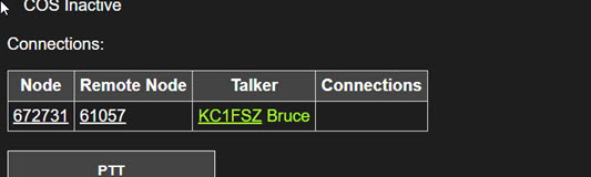
The conference bridge inside of the Ampersand node transmits the TALKERID corresponding to whichever line the current audio activity is coming from. Any time the source of the audio changes (i.e. when a new person starts talking or when the TALKERID associated with a node connection in a conference hub switches) the TALKERID telemetry message should be sent to all connected nodes that are receiving the audio feed. The TALKERID is re-asserted every 10 seconds for the benefit of a newly-connected node that missed the last talker change.
There is no special handling of the case when two nodes are talking into a conference bridge at exactly the same time. The decision about which talker ID to forward to the node output is arbitrary in this case, and not worth getting too worried about.
This protocol does not expose the path across which the audio originated, although that could be interesting for debugging purposes.
If a node is being used as a bridge to some other digital network technology that supports a similar concept, it should be enhanced to forward the analogous talker ID. I am not familar enough with the DMR/D-Star/YSF bridges to know how this would work, but I’m sure it’s possible.
If a node is being unsed as link to an analog radio/repeater system where no information about the actual talker is available the callsign of the station itself should be used.
Obviously this feature isn’t supported on the existing ASL network. Ideally the concept can be refined and then widely implemented so that talker information will be fully propagated to all network end-points sometime in my lifetime.
NOTE: Thanks to Allan (WA3WCO) for pointing out this ASL Enhancement Request. It seems like there is another IAX2 text message “K” (for “keyed”) that is potentially related to this. Although not implemented fully. If nodes could pass forward the keyed status of nodes from which audio is being received - specifically which contributing node was keyed - this could help a lot. The problem of converting the node number to more friendly text would still need to be solved, but there’s likely an ASL HTTP API for that already.
Microcontroller Version
(More docs to follow)
Some YouTube demos:
VOTER Implementation
This is a big topic and it deserves a section to itself. I won’t repeat all of the VOTER documentation, please see these sources for more detail:
- About VOTER
- The VOTER Protocol
- An important reference from KC2IRV that talks about synchronization requirements.
- A good intro video on simulcast.
- A video about simulcast systems
- An article that gives some parameters.
- An interesting article that talks about the risks to public safety communications.
Some other VOTER projects:
- The RTCM VOTER Firmware
- VOTER2 which appears to be specific to the MTR-2000.
VOTER Protocol Documentation
There are some gaps in the VOTER protcol documentation so these notes should be considered a supplement to the official VOTER protocol documentation.
Regarding the Header Fractional Time (Octets 4-7)
The documentation states that there are two cases for this field:
- In normal mode the field contains the fractional time in nanoseconds.
- In general-purpose (mixer) mode the field contains a sequence number.
In normal mode the time appears to be an even multiple of 0.02s, or 20,000,000ns.
Will (N0XGA) provided this information about general-purpose mode:
For General Purpose packets the nanosecond field does indeed increment by one for every packet and the seconds is just unix time. Importantly, that packet counter still increments even if there are no packets sent! That is, the packet counter counts up by 1 every 20ms even if the client isn’t sending any packets, so if you have a 1 second pause in reception, the first packet after the pause will be +20 from the last packet. Note also that the spec says if you are using ADPCM that only send a packet every 40ms, the packet counter increments by two. Put more simply, the “packet count” is really just a counter value that starts at 0 at boot and increments every 20ms no matter what. That is how I ended up coding it.
I think he meant to say “+50 from the last packet” above, but the point still stands.
Small Documentation Error - Ping Packet Size
The beleive the VOTER Protocol documentation contains a small but important error. The definition of PING reads as follows:
Payload type 5 - “PING” (Connectivity Test) Octets 24 and up contain 200 bytes of payload for evaluation of connectivity quality. When a client receives this packet, it is intended to be transmitted (with the payload information intact) immediately back to the host from which it came. The actual contents of the payload are not specifically defined for the purposes of this protocol, and is entirely determined by the implementation of the applicable function in the host.
This suggests that the PING message can be 24 + 200 = 224 octets in length. However, after some strange problems and a review of the VOTER firmware I can see that the static/global buffer allocated for reading the PING messages is only 24 + 164 = 188 bytes in length. Unforunately, sending the bytes above the 188 byte limit may result in a write into an unexpected area of memory in the VOTER/RTCM device. BE CAREFUL!
GPS Interface Notes
Voter clients use a GPS/GNSS module to establish a precise time reference. There are two parts to the GPS interface:
- The serial NMEA messages (ex:
$GPRMC,194013,A,4032.94888,N,10511.83890,W,0.005,,020121,,,D*62) - The PPS signal, which pulses once per second and would generally be used to trigger an interrupt.
The serial messages are used at the beginning of the synchronization process to establish the location and to obtain the full YYYY-MM-DD HH:MM:SS date/time. Once the PPS signal is pulsing regularly and a valid GPS/GNSS “fix” has been obtained the only thing that the serial messages are used for is to monitor the continued validity of the fix - there is no further need for the location/time information since the location is assumed to be constant and the time is being incremented by the PPS interrupt.
The number of satelites in view is taken from the $GPGSV message. The time/date is taken from the $GPRMC message. The validity of the fix is taken from the $GPGGS message.
GNGGA Message
This is a more general version of the GPGGA message (GPS only). GNGGA includes other constelations.
Example:
$GNGGA,141147.000,,,,,0,00,25.5,,,,,,*7C
- UTC Of Fix: 141147.000
- GPS Quality Indicator: 0 (Fix Not Valid)
-
Number of SVs in use: 00
$GNGGA,153808.000,4218.22204,N,07118.08341,W,1,07,2.7,44.3,M,-28.9,M,,*40
- UTC Of Fix: 133808.000
- GPS Quality Indicator: 1 (GPS Fix)
GPGSV
$GPGSV indicates GPS and SBAS satellites.
Example:
$GPGSV,1,1,02,01,,,13,14,,,22,0*61
- Total number of messages of this type in this cycle: 1
- Message number: 1
- Total number of SVs visible: 02
- Repating block
- PRN number: 01
- Evevation
- Azmuth
- SNR
Example when multiple satelites are in view.
$GPGSV,3,1,11,01,64,085,22,02,36,049,10,03,15,129,25,07,21,186,,0*63
$GPGSV,3,2,11,08,12,074,,13,06,277,,14,71,313,16,17,51,273,27,0*6E
$GPGSV,3,3,11,19,23,260,,22,55,310,,30,42,218,27,0*51
- Total number of SVs visible: 11
GPRMC
Provides the date/time detail that is applicable to the last PPS signal. So the arrival of this serial message isn’t useful for precise timing, but it is very important to process it quickly (before the end of the current second).
Examples with time/date alignment shown below:
$GPRMC,194013,A,4032.94888,N,10511.83890,W,0.005,,020121,,,D*62
       hhmmss                                     ddmmyy

$GNRMC,141704.000,V,,,,,,,240326,,,N,V*2F
       hhmmss             ddmmyy

$GPRMC,170047.00,A,4121.23302,N,00201.31654,W,2.703,   ,200417,   , ,A*64
$GPRMC,hhmmss.ss,A,llll.ll,   a,yyyyy.yy,   a,x.x,  x.x,ddmmyy,x.x,a,m*hh
       |         | |          | |           | |     |   |      |   | | \- 13 Checksum
       |         | |          | |           | |     |   |      |   | \--- 12 Mode indicator, (A=Autonomous, D=Differential, E=Estimated, N=Data not valid)
       |         | |          | |           | |     |   |      |   \----- 11 E or W of magnetic variation
       |         | |          | |           | |     |   |      \--------- 10 Magnetic variation degrees (Easterly var. subtracts from true course)
       |         | |          | |           | |     |   \----------------  9 UTC date of fix
       |         | |          | |           | |     \--------------------  8 Track made good in degrees True
       |         | |          | |           | \--------------------------  7 Speed over ground in knots
       |         | |          | |           \----------------------------  6 E or W of longitude
       |         | |          | \----------------------------------------  5 Longitude of fix
       |         | |          \------------------------------------------  4 N or S of latitude
       |         | \-----------------------------------------------------  3 Latitude of fix
       |         \-------------------------------------------------------  2 Data status (A=Valid position, V=navigation receiver warning)
       \-----------------------------------------------------------------  1 UTC time of fix
Synchronization of Audio with GPS Clock
The audio quality of the VOTER system depends on synchronization of the audio sampling clocks across the network. A GPS or NTP reference clock is used to achieve this synchronization.
The original Jim Dixon VOTER design used a 9.6 MHz oscillator as the master clock for the PIC microprocessor. This clock is divided down by an integer to obtain the 8kHz audio sampling clock. Because the PIC chip used in the design has an integrated ADC and DAC, the required analog-to-digital and digital-to-analog conversions can be performed by a timer-driven interrupt service routine (ISR) that runs on every 8 kHz “tick.”
The use of integrated ADC/DACs makes the hardware simpler, but it also limits the range of microcontrollers that can be used for this application. Furthermore, the integrated ADC/DACs tend to have lower performance specifications that modern CODECs designed specifically for audio applications. The most common integrated ADCs seem to have 12-bits of resolution, as compared to 16-bit for the CM108 used in other parts of the AllStar network.
The ISR-driven sample clock architecture may also be limiting at higher audio rates. Digital audio systems usually address this problem using a direct-memory access (DMA) approach.
Can the required audio synchronization be achieved using DMA transfer, possibly to an external CODEC?
Exploration of GPS-less Voting
Jim Dixon’s (W6BIL) design of the AllStar VOTER is impressive. I don’t know a lot about advanced repeaters, but I do know that voting (receive) and simulcasting (transmit) capabilities exist in very expensive commercial/public-safety radio systems. The fact that hams have access to these functions using hardware that can be built/bought for a few hundred dollars is amazing.
From what I can see, the key concept that underlies the VOTER system is synchronization. The synchronization requirements on receive and transmit are different. In this section I am only focused on the receive (voter) side of the problem. I’ll write more about synchronized transmit (simulcast) in a different section.
The following paragraph from Jim’s documentation lays out the challenge:
The main problem to overcome is that when you have multiple streams of audio information from multiple receivers, you need a concise and accurate way of synchronizing all of the audio, so that if switching of streams occurs, there will be no inconsistencies in the audio. This is far more easily done on conventional, RF-linked voting systems, being that the delay between the receiver and the transmitter site is very minimal (basically the speed of light) and is painfully consistent. Not so on the Internet. The packet delays can be extremely long and varied, and it makes the task of synchronization far more difficult.
From my testing of various parts of the Ampersand system, and in particular my attempts to build a smooth packet loss concealment (PLC) algorithm, I can attest that what Jim said above is true. It doesn’t take much of a discontinuity in the audio stream to create a click, pop, or other audible artifact.
The original VOTER design employs a clever solution to solve the audio stream synchronization problem: a GPS-derived clock. This can be achieved using an inexpensive GPS/GNSS module.
Given multiple audio streams collected from multiple receivers across a voting network, the job of reconciling and choosing the “winning” stream happens inside of the central VOTER server. One of the best things about GPS synchronization of the audio streams is that the server’s job becomes very easy. Each 20ms audio frame is timestamped with a GPS time (rounded to the nearest 20ms interval) so the server just needs to buffer these frames, line them up, and select the best one at each audio tick. There is very little computation required to perform this job.
Of course even this scheme doesn’t provide a “perfect” solution. As was pointed out to me by Mason (N5LSN), even with perfect synchronization the receivers will rarely hear the exact same thing at the exact same time. Depending on the differing distances of the transmitting station from the receivers, the speed of light (~1 mile per 5.2uS) enters into the calculation. A 20 mile distance between receivers results in a ~100uS misalignment in audio streams, even with a “perfect” time reference/synchronizations system.
The question I’ve been wondering about is: do you really need GPS to achieve the required accuracy? Is there a way to make the hardware even simpler?
I became more interested in this question after coming across this paper published in the 2007 IEEE International Conference on Communications. The authors of this paper were exploring the potential of non-GPS time synchronization methods for use in simulcast transmitters in an FM-analog UHF repeater system. From what I can tell, the requirements for simulcast are much more stringent than they are for receiver voting. The paper proposes the use of plain-old Network Time Protocol (NTP) instead of GPS to obtain the necessary time sync.
(As an aside, it seems that the authors of this paper were focused on GPS-free solutions as a way to eliminate dependencies on US government-operated systems or possibly to address situations when GPS reception was not reliable. The policitcal issue is probably less important now given the diversity of navigation systems in orbit. However, the reliability issue is more accute now than it was in 2007 given the deployment of GPS-jamming technology. Neither of these motivations seem particularly relevant in the ham repeater context, but the technical problem is still highly relevant. I might think of this differently if some adversary started GPS-jamming our club’s Wednesday night net!)
Based on my initial testing, I don’t think you need GPS to do receiver voting, assuming you’re willing to do some calculations on the server side of the voter system. My reasoning is summarized below. Send me a comment if you think I’m looking at this the wrong way.
When Does Synchronization Matter?
When a single VOTER client is streaming audio to a VOTER server precise time synchronization isn’t important. The audio playout will be smooth as long as the client is sampling at a rate very close to 8kHz and the network packets are arriving at the server on time. In this case the timing requirements are no different from any other AllStar audio stream flowing between nodes.
Precision starts to matter in the transitions between voting receivers. If the switch between one active receiver and another results in a sudden/discontinuous jump in the audio samples an annoying pop will be audible. Even worse, if the audio stream moves ahead/behind enough to hide/duplicate a syllable then the intelligibility of the QSO starts to degrade. The VOTER design uses the GPS time stamps to align audio streams closely to minimize these unnatural “jumps.”
This research focuses on the handling of receiver switches in a different way.
NTP on a Microcontroller
The NTP protocol was introduced in 1985. To paraphrase an old joke: I could get into a detailed explanation of NTP, but I don’t have the time. Suffice to say, the protocol is very simple. An NTP client can be implemented on a microcontroller easily. Michael (N5ZR) has demonstrated NTP on an ESP32. I built my implementation on an RP2040 controller that was also connected to a GPS/GNSS module in order to calibrate. My conclusion is that a microcontroller’s onboard clock can easily maintain synchronization to within about 4ms of “GPS time.” Even better synchronization can probably be achieved with more sophisticated methods, assuming the controller’s crystal oscillator is of reasonable quality. No OCXO/TCXO is required, but the “normal” oscillator needs to be pretty good.
Here’s a screen shot captured from a test run:
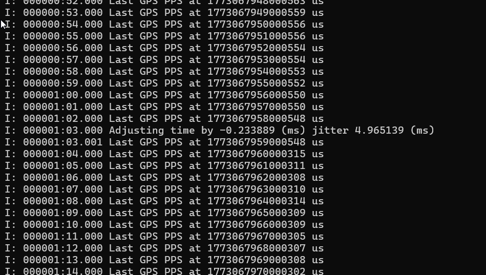
This shows a few things:
- Each “Last GPS PPS” line shows the time observed when the GPS module’s PPS signal ticks. As you can see, the time in microseconds (the long number starting with 177) is drifting by about 4 microseconds per second. This demonstrates the inaccuracy/instability of the microcontroller crystal. But keep this in perspective - an audio sample happens once every 125uS so a few uS of drift in a second doesn’t create a noticeable problem.
- The NTP-derived time observed on the PPS ticks has pretty good phase alignment. There are three zeros in all of the time stamps. We are able to find the beginning of each GPS second with decent accuracy.
- The “Adjusting Time” line shows when the NTP algorithm steps in to correct the microccontroller’s clock. This happens every minute or so and should help to clean up some of the drift.
Using this approach we can build VOTER packet timestamps that would allow the server to synchronize audio streams to within ~4ms of each other. However, testing shows that this isn’t good enough to achieve high-quality voter audio.
A Little Help From DSP
Further adjustments to the audio stream are required to eliminate the potential 4ms alignment problem. After some testing, I’ve come up with a few approaches to this problem.
When multiple receivers are “hearing” the same transmitting station, the voter logic uses RSSI values to select which will contribute its audio to the AllStar conference. Only one receiver is selected by the voter at a time. However, the audio streams from all eligible receivers are available in the server for examination. When multiple streams are available, the streams will differ from each other in a few ways:
- They will have different noise levels, which is the whole point of a voter system.
- They may differ in amplitude, depending on how well matched the receivers are.
- They may differ in phase, depending on how well the sampling clocks are synchronized and how far the receivers/transmitters are from each other.
However, the fact remains that all streams will bear a strong resemblance to each other given that they all originate from the same transmitter. This “strong resemblance” can be quantified using DSP techniques: specifically, a cross-correlation between the streams.
Streams that differ in noise level and amplitude will show a strong cross-correlation. However, streams that differ in time synchronization (phase) will not correlate strongly and, in extreme cases, may even exhibit negative cross-correlation.
I’ve found that a good way to get an accurate estimate of the phase delay of one stream with respect to another is to evaluate the cross-correlation across a range of time delays. Assuming that the NTP clock synchronization method can bring the streams to within ~4ms of each other, cross-correlations using delays from -2ms to +2ms can be evaluated until a peak is found. The offset that results from this search provides a highly accurate measurement of how much one stream needs to be advanced/delayed to provide a smooth transition during a switch from another. Given that the time offset between streams moves very slowly, the offset calculated using this method should be quite sticky.
This process of “searching” for the optimal phase adjustment is a problem that is often referred to in the DSP literature as “phase correlation.” It’s a problem that shows up in many signal-processing contexts (radar esp.) so there are plenty of techniques to be borrowed. Advanced algorithms start the search for the best delay using a coarse grid and then refine the step size as the search space is narrowed. My approach is a simple linear search through the range of possible delays.
Once the relative offset between two streams is determined, the range of offsets that needs to be tested to keep the streams in sync with each other becomes narrower. Ideally, some kind of software phase-locked loop can be used to track the error and adjust it smoothly. Jitter is certainly significant when it comes to the arrival of voice packets from the network, but that isn’t relevant to the tracking of the sampling clock. The jitter (aka phase noise) of the sampling clock itself is a much smaller problem - a handful of microseconds per second as shown in the NTP test above. Ironically, the thing that is most likely to invalidate the correlation-based offset estimate between two audio streams is the NTP-driven clock correction process running in the clients. For this reason, it might make sense to suspend (or at least slow down) NTP synchronizations for a client that is actively receiving. I’m thinking that the ~150 bytes of “implementation defined” payload in the PING message (payload type 5) provided by Jim’s protocol might be used to keep the clients apprised of where they stand in the voting process.
Unlike many things in the AllStar system that run at the audio frame level (i.e. 20ms of audio), this algorithm must run at or near the sample level (125uS). Assuming the range of potential offset errors is within +/-2ms, only 32 trials are needed to narrow the accuracy to the 125uS level that is theoretically achievable using the GPS clock synchronization. The algorithm I have chosen evaluates the cross-correlation on the trailing three frames of audio (60ms) which gives more than enough samples to establish a strong cross-correlation between two phase-matched (but noisy) versions of the same transmission.
It’s also worth noting that the default “linger” parameter in the AllStar VOTER implementation is 120ms. This leaves plenty of time to analyze cross-correlations between the active receiver and the next-best candidates before needing to make a switch.
Finally, another technique that can be used to minimize pops/clicks resulting from receiver switching is to blend the transition from one stream to another. My implementation performs a linear cross-fade between the “old” and “new” receiver. A raised-cosine transition would have even less spectral content.
One Test
This audio recording provides a demonstration of the result of this algorithm. This was made using a bench simulation that I hope resembles a real-world scenario.
The test starts with an 8K audio recording captured from a real AllStar node. This is called stream A.
Stream B is made by copying stream A, offsetting it by 4ms, and applying a gain of about +1dB. This simulates a second receiver hearing the same audio with a slightly different level setting and an extreme imperfection in clock synchronization.
Next, white noise with a level of -35dBFS was added to both streams. Different noise was used for streams A and B to simulate uncorrelated noise at two different receiver locations.
Next, a simulated RSSI feed was connected to each stream that would cause the voting logic to switch between streams A and B every second. I think this represents an extreme case.
Next, these two streams (plus the RSSI data) were converted to standard VOTER protocol format and fed into the Ampersand VOTER server implementation. The output is captured in the recording linked above.
Even though the audio streams were significantly out of phase and switched back and forth nearly 120 times during the 2 minute clip, to my ear it’s hard to detect any voter-related artifacts in the recording. I’m guessing the repeater connoisseurs may be able to hear a defect or two …
How Robust is Cross-Correlation?
Here’s a test that demonstrates the effectiveness of the DSP. In this test, the two receive streams are offset by 2ms and are both added to loud, independent white noise sources of -8dBFS. As you can tell from this recording, the QSO is barely audible above the noise.
A histogram of the cross-correlation search was created that covers the first 5 seconds of the clip. As can be seen from the chart, the search still “locks” onto the 2ms phase error despite the poor conditions.
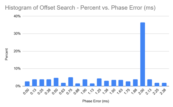
The ~35% hit rate doesn’t seem great, until you compare it to all of the other possible offsets at any point in time. Going with the maximum likelihood offset gets you to the right answer.
Which NTP Server?
My testing was performed using time-a.nist.gov (129.6.15.28), a Stratum 1 NIST Internet Time Service server located in Gaithersburg, Maryland. One could argue that a weakness of my design
is that it depends on (a) the public internet and (b) the reliabilty of the NIST
infrastructure. The authors of the 2007 conference paper would surely object to the fact that
NIST is a US-controlled entity.
I have not tested this, but it is my belief that the use of a fancy US-based “stratum 1” NTP source is not important. What is important is that all clients in a voter network are synchronized to the same time source. It would probably make sense to add an NTP server onto the VOTER server to allow clients to derive their timing synchronization from a central, independent source. (Geopolitical alignments could also be taken into account when making this selection, as needed.)
To take this even further, I note that Jim (W6BIL)’s VOTER protocol design contains a PING connectivty test message type. Given this nice statement from Jim:
The actual contents of the payload are not specifically defined for the purposes of this protocol, and is entirely determined by the implementation of the applicable function in the host.
the PING protocol could probably carry NTP-like time synchronization content which could eliminate the need for out-of-band timing protocols entirely. This is something for future research.
The one advantage of using a legit stratum 1 NTP server is that it allows GPS-based clients and NTP-based clients to be mixed in the same voter network.
Conclusion
It should be noted that in 2011 when the VOTER system was originally designed the CPU resources needed to perform some of these DSP alignment tricks in real-time were much more expensive. At that time it made a lot of sense to leverage GPS-disciplined clocks. Given the processing power available to us now, the same problem can probably be solved in a different, more software-oriented way.
I hope that this research can help others to create even simpler/cheaper voter clients.
Othe VOTER Stuff
- RSSI: https://pmc.ncbi.nlm.nih.gov/articles/PMC9499186/
Other Pages
- Notes on Receive Audio Level Calibration
- ASL DSP Notes
- 55553 Parrot
- Notes on Audio Latency, Jitter, and Related Topics
References/Books
- The IAX2 RFC.
- I highly recommend Spectral Audio Signal Processing by Julius Smith from Stamford. The text of this book is available online at Stamford or you can get the physical book.