IBM 1620 - Input-Output Typewriter, Interface Mechanics
In a previous post I talked about the Model B Electric Typewriter that served as the I/O device for the original 1620 models. In this post I’ll start to get into the complex mechanics and electronics used to integrate the 1620 with this typewriter.
It’s no surprise that the typewriter itself is a mechanical device. What was surprising to me is how much of the typewriter interface is also mechanical. The logic of the core 1620 processor used a cutting-edge transistorized design. In contrast, the typewriter interface was built from a bewildering collection of mechanical relays, motors, and spinning cams. My guess is that either (a) this part of the system was designed before the SMS/transistor technology was firmly established or (b) this part of the system was designed by the “typewriter team” who had deep expertise/history building complex machines but was less comfortable with transistors. It seems to me that the 1620 typewriter controller stood at the cross-roads between the IBM/CTR mechanical calculation/tabulation legacy and the future of electronic computing.
A chapter entitled “Commutation and Control” from an unknown IBM document archived on the IBM-1401.info site provides illustrations of the IBM electro-mechanical devices used in a wide range of machines of the era. In this post I’ll summarize the key concepts that are needed to understand how the 1620 typewriter interface works. Some concepts are clear from the IBM documentation, other concepts take some digging to understand.
Duo Relay
This is the most common component used in the 1620 typewriter interface - there are about 50 of them! The IBM documentation refers to the basic relay as a “Duo Relay” for reasons that we’ll get into shortly.
Most people are familiar with the operation of a relay so I’ll just highlight the facets that are most relevant to the 1620 design:
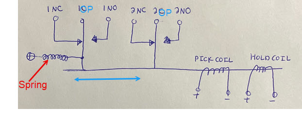
- The duo relays support multiple/parallel contact sets known as “stacks.” The picture above shows two contact sets (1NC/1C/1NO and 2NC/2C/2NO). NC is “normally closed,” OP is “common” or “operating point” and NO is “normally open.” The 1620 uses relays that have up to 12 independent stacks controlled by a shared set of coils. NOTE: My crude diagram above is misleading in that it appears to show that the 1OP and 2OP contacts are connected - they are not, each stack is electrically independent (although they are mechanically connected).
- The relay is closed when the coils are energized. IBM uses the term “pick” to refer to the relay closing operation. I’ve seen the term “relay pickup” used in common literature, so “pick” must be an abbreviation. The IBM documents use the word “pick” as a noun qualifier (when describing the purpose of a coil) and as a verb to describe the action of “picking” (closing) a relay.
- The term “duo” arises from an interesting feature that I’ve not seen before. Notice from the diagram above that there are two separate coils provided for operating the relay. The pick coil is designed to close the relay and the “hold” coil is designed to keep it closed. Why two coils? It turns out that the pick coil was engineered to operate quickly, at the expense of higher power. The hold coil, on the other hand, works more slowly but consumes less power. The difference has to do with the type/amount of wire used to wind the coils. Control circuits are designed to energize the pick coil first in order to quickly close the relay, and then hand over to the hold coil to keep it closed for a longer period of time. This is obviously a highly refined form of electromechanical engineering. Importantly, one of the two coils must always be energized to keep the relay closed or else the spring will pull it back to its normally-open state again.
The relay parts are disaggregated in the 1620 schematics. This part of the schematic (page 01.82.72.1) shows two stacks of relay 3: stack 4 and stack 2, but not their coils. Notice each stack has three connections (NC/OP/NO). These two stacks are electrically independent, except for the fact that they are controlled by the same two relay coils.
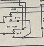
Coils and other stacks of the same relay may appear on completely different pages in the schematic, which can be confusing.
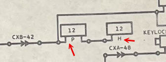
This part of the schematic (page 01.82.72.1) shows the two coils for relay 12. The “P” indicates the pick coil and the “H” indicates the hold coil. (NOTE: This particular example is unusual in that the two coils are wired in series - that defeats the purpose of the duo relay since the two coils are energized simultaneously.)
Latching Relay
This is less common, but appears in some critical functions of the 1620.
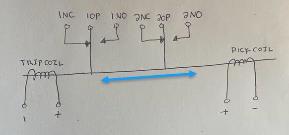
The key difference here is that the relay has no spring. Once the pick coil is energized, the relay will stay closed even when the current is removed from the coil. IBM uses the term “trip” to refer to the opposite movement: once the trip coil is energized the relay opens again. There is no power required to maintain the closed or open states - only to transition between them. This relay type is used to manage long-lived states in a power-efficient manner.
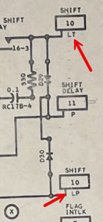
There is no difference in the depiction of the duo vs. latching contacts in the schematics. The schematic representation (page 01.82.72.1) of the latching coils use “LP” to denote the pick coil and “LT” to denote the trip coil:
Cam Operated Relays
This one took some time to figure out. The surprisingly complex timing sequences needed by the typewriter interface are driven by a special type of rotating relay called a cam-operated contact. In this device, a motor is used to turn a series of parallel cams to produce electrical continuity at different phases of each rotation. The precise phasing is achieved by (a) choosing the size of the cam to control the fraction of the rotation for which it is engaged and (b) offsetting each cam relative to the others on the same drive shaft to determine the phase of the engagement. This is very similar to the camshaft in a mechanically-controlled engine.
This picture from the IBM documentation illustrates the mechanism:
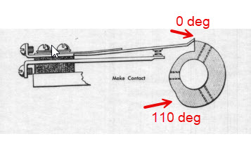
The cam rotates in the clockwise direction. Notice that the relay contact is held open from approximately 110° around to approximately 360° and is allowed to close from 0° to 110°. The point where the relay closes is called the “make angle” and the point where the relay opens is called the “break angle.” A complicated machine like the IBM 1620 typewriter interface would typically have several cams mounted on the same motor shaft, each sized and offset differently to produce the desired timing pulses.
These devices show up in the 1620 schematic in a cryptic way that only makes sense when you understand the mechanics. Here is an example (page 01.82.72.1):
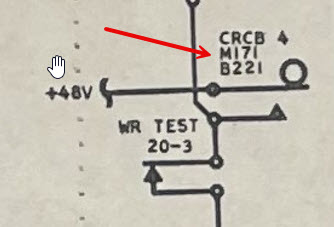
“CRCB 4” is the 4th of 6 parallel cams mounted on the same motor shaft. M171 means that the relay is “made” (closed) at 171° of rotation and B221 means the relay “break” is at 221°. If you do the math, this cam provides a repeating pulse with about a 14% duty cycle: (221 - 171) / 360.
Note in this example, when CRCB 4 is made we expect to see +48 volts on the operating point of stack 3 of relay 20.
Here we see CRCB 6 (page 01.82.70.1), which is another instance of the same 50° cam part, but offset at a different phase relative to CRCB 4. This produces another 14% duty cycle pulse, but offset from CRCB 4 by 139° in phase.

With this context you can start to interpret the puzzling timing figures shown in the CE Manual of Instruction that reference angles:
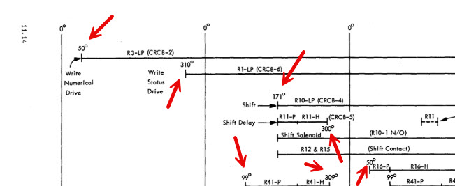
Hopefully you can see that this is the mechanical equivalent of the electronic clock sequence that was described in my previous post about clocking. The main difference is that the “modern” SMS electronic sequence runs at a speed 4-5 orders of magnitude faster than the spinning motors and switching relays. That said, the sound of the typewriter system must have been very cool, in a steampunk kind of way. :-)
Contacts
This is a simple device, but it’s worth calling out to avoid confusion. A “contact” refers to a normal switch. I mention this here because the schematic can easily be confused with a relay. Here is an example (page 01.82.70.1):
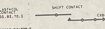
There are no numbers on this device - just the name, ex: “SHIFT CONTACT.” This particular switch was added to the typewriter to signal when the basket upshift is completely engaged. The schematic symbol indicates that the switch is normally open.
Simulation Notes
Needless to say, there are no simple SPICE/Verilog representations of many of the components described above. It would be theoretically possible to reverse-engineer an equivalent boolean logic representation of the assembly of the 12 pages of schematics showing the myriad of switches, duo relays, latching relays, and cam contacts, but that is a lot of work and runs the risk of missing an important facet of the circuit. Instead, I am pursing a more analog approach to this simulation that takes the components as they appear on the pages. In fact, this part of the 1620 circuit represents an interesting hybrid simulation problem that needs to combine three cooperating domains:
- The “traditional” SMS logic cards that can be reasonably modeled using Verilog logic simulation techniques (with more caveats that I am learning as I go along).
- Analog circuitry that deals with +48V connections, cascaded relay coils, and very complex circuit paths that orchestrate the many moving parts (literally) of this design.
- Mechanical components that create linkages across different parts of the circuit. For example, the relay coil and relay contacts are “connected” via a mechanical behavior that needs to exist for the simulation to work.
My approach has been to focus on capturing an accurate representation of the electrical/mechanical components and their inter-connections without attempting to translate this into modern “digital Verilog”, or even to understand the purpose of each component. I then run the simulation using a hybrid analog/mechanical technique. This approach has been successful so far, and allows the larger purpose of the circuit (i.e. energizing solenoids connected to specific keys on the typewriter in careful sequence) to emerge. More on this to follow.