IBM 1620 - The Missing Link (One of Many, I'm Sure)
In a previous post I explained some of the mechanical aspects of the 1620 typewriter interface. After I had recorded the ~20 schematic pages that make up that circuit and started doing some simulation I struggled to get the simulated typewriter to output anything. I’ve never physically seen a 1620 and I’ll admit that I don’t understand much of this complex circuit, but I was pretty confident that all of the connections were coded properly. I have found a few small bugs in these non-ALD diagrams along the way, so there is always that possibility in the back of my mind, but the behavior I was seeing (or not seeing) seemed more fundamental.
This led to the discovery of what I’m calling the “missing link” - or at least one example of many potentially-missing links.
What’s Not Shown in the Electrical Schematics
I’ve been working from a set of schematics kindly loaned to me by Dave Babcock. The pages used to describe the 1620’s I/O system (including the typewriter) are different from the rest of the diagrams because they aren’t implemented using “normal” SMS cards. Strictly speaking, these pages are not ALDs. I/O devices live in the physical world and involve control over a lot of whirring/moving/spinning/clicking mechanical parts, as described in my previous post. This would be a clock-maker’s paradise.
The reason that my simulated typewriter wasn’t typing is a good illustration of something to be on the lookout for in the future.
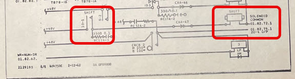
Pages 01.82.70.1 and 01.82.72.1 have some important parts, all marked below.
On the right of this diagram we have the solenoid marked “SHIFT” that resides inside the typewriter that physically pulls down the shift key on the command of the interface circuit. On the left side we have the relay contacts (10-1) that connects that solenoid to +48V when a pull is needed.
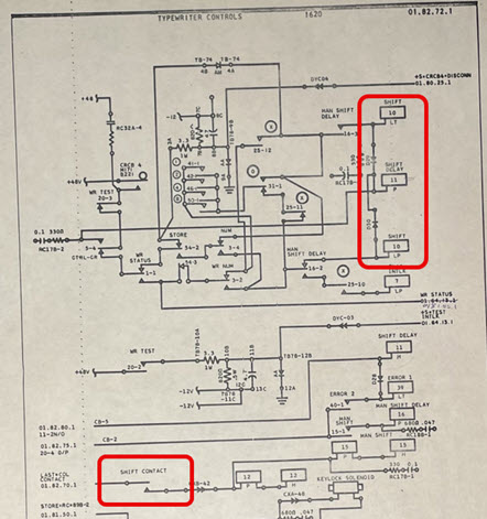
On the right side of this diagram we have the pick and trip coils for latching relay 10. On the left bottom we have a switch marked “SHIFT CONTACT.”
What is important to understand (and not obvious at first glance, but later glaringly obvious) is that there are SIX components that are all linked. It’s just that those linkages aren’t apparent from the schematic in all cases. Here’s the way I see it:
- The relay 10 coils are electrically controlled by the circuit that comes before.
- The relay 10-1 contacts are mechanically controlled by relay 10 coils from #1 above (even though they are on completely different pages of the schematics.)
- The SHIFT solenoid is electrically controlled by the relay 10-1 contacts.
- The typewriter “basket” (see this post for more) is mechanically controlled by the SHIFT solenoid. The basket gets physically lifted up. Check out this video to see what that looks like.
- The SHIFT CONTACT is mechanically controlled by the basket. That switch was added to provide instrumentation of the internal state of the typewriter.
- The rest of the circuit that follows is electrically controlled by the SHIFT CONTACT switch.
What I was missing was linkage #5 above: the switch is controlled as a result of the basket movement. I won’t bore you with the details, but essentially the complex state machine in the 1620 typewriter interface was “stuck” waiting for the basket to finish its up transit. NOTE: There is no concept of a “timeout” in this circuit. HA. :-) Once that mechanical linkage was represented in the simulation, things started typing!
BTW, this is an illustration of good design by the team at IBM. As was highlighted in a previous post, the “basket raise” operation can take around 100ms to complete. Instead of baking that time into the system and assuming that the basket was in place, the design team provided what amounts to a feedback path through the circuit. Only when the basket is actually raised does the next step in the sequence happen. The potential race-condition is eliminated.
I share this to highlight what I’ve come to realize.
- This is a very interesting hybrid simulation project.
- The more accurately the simulation represents the physical/electrical reality of this system, the less detailed my understanding of the inner logic of the 1620 needs to be. As I’ve mentioned, there are around 50 relays being used to implement the typewriter output interface, but I have very little understanding of what most of them do. I hope to keep in that way. Life is too short.